
E3510 Car radio
- Make
- Alfa Romeo
- Model
- 156 Factory Service Manual
- Year
- 1997–2002
- Section
- Radio accessories › E3510 Car radio
E3510 Car radio
Description
The vehicle is prepared for the installation of a radio system.
This preparation comprises:
- radio compartment
- radio supply cables
- separate front power and tweeter speakers, located in the doors;
- rear speakers, located in the doors;
- rear speakers on the rear parcel shelf
- leads connecting the radio to the speakers;
- aerial built into the heated rear windscreen by means of a suitable electronic device and connected to the radio through a coaxial cable.
The radio circuit is supplied with the key turned to the ON position, or directly from the battery (which allows tuning settings, security codes, etc. to be stored).
The above two lines are protected by a fuse in the junction unit.
In addition to the radio there is also a supply with the side lights on to light up the radio controls.
On request, a radio specially designed for this car may be fitted during production. There are two different types to choose from. Full radio specifications and operating instructions are given in the OWNER'S HANDBOOK.
Several anti-interference suppressors have been fitted to the wiring to silence all those electrical consumers which could interfere with the radio circuit.
A multi-polar cable, connecting the radio with the CD player, located in the boot, can be fitted on request.
Description of operation
The radio P20 is supplied directly (pins 4 and 7 of connector A) by the battery via the line for fuse F10 of junction unit B1 and maxifuse J/B1 of B5 up to 2/99 or B99 from 2/99.
It receives a supply when the ignition is switched on (INT) (pin 3 of connector A) via the line for fuse F1 of the junction unit B1.
With the side lights switched on, the supply reaches pin 6 of connector A by means of the line coming from the switch for the steering column switch unit H5, protected by the controls illumination fuse B11 up to 2/99 or fuse F4 of the additional fuse box B98B from 2/99; the radio controls are therefore lit up when the lide lights are switched on.
Pin 8 of connector A, on the other hand, is earthed (C20).
Pin 5 of connector A is connected to the control unit P22 which controls the aerial built into the heated rear windscreen. The control unit P22 is then connected to the radio by means of the specific aerial lead.
Connector B sends out cables carrying signals to the speakers:
- pins 5 and 6 to the left front speakers P35 and P45,
- pins 3 and 4 to the right front speakers P36 and P46,
- pins 7 and 8 to the left rear speakers P30 and P40,
- pins 1 and 2 to the right rear speakers P31 and P41.
Wiring diagram
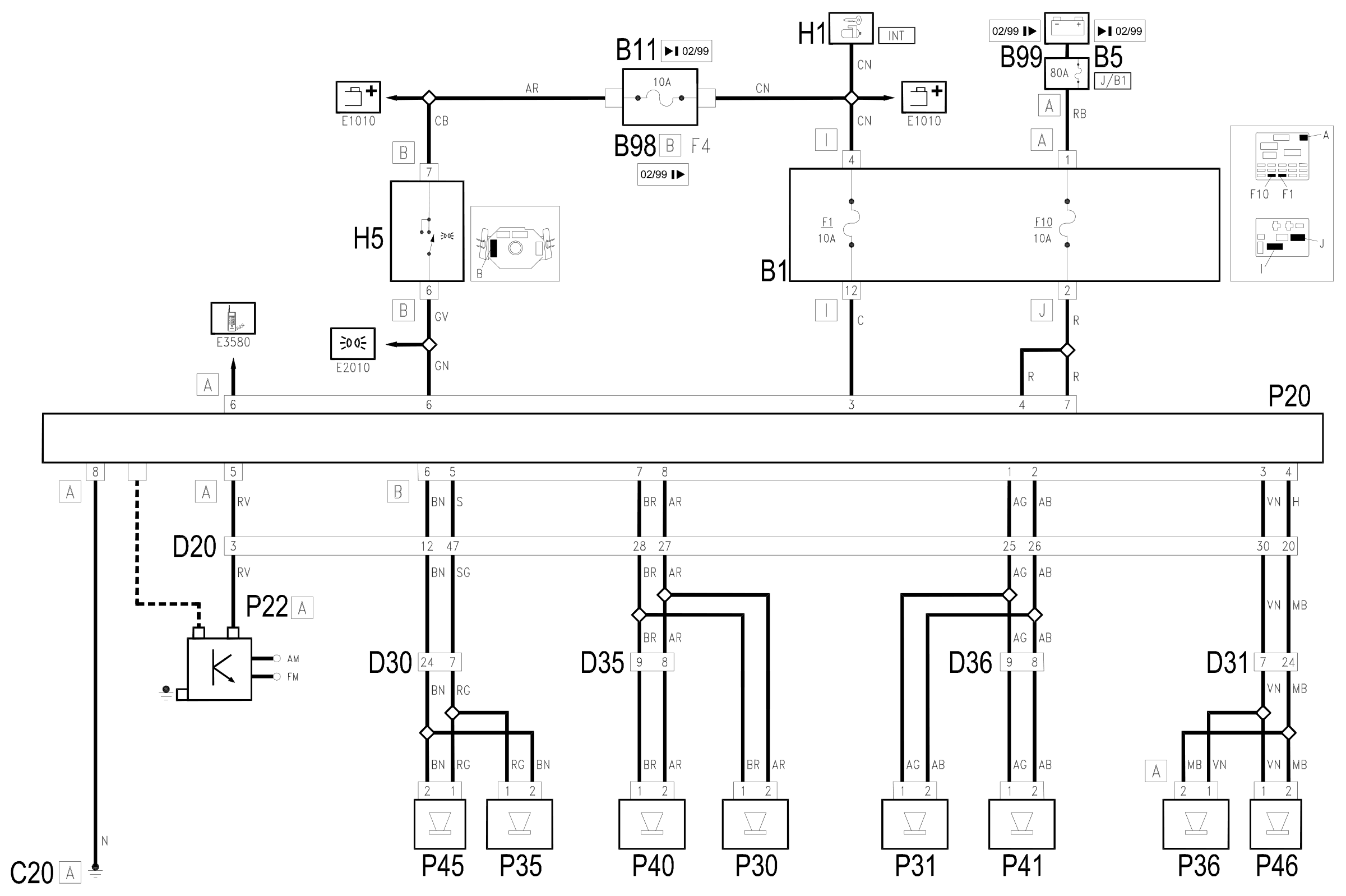
Components
| Code | Component | See |
|---|---|---|
| B01 | Junction unit | description 5505A |
| B05 | MAXI FUSE-1 box | |
| B11 | Controls lighting fuse | |
| B98 | Supplementary fuse box | description 5505A |
| B99 | Maxifuse box on battery | |
| C20 | Passenger side dashboard earth | description 5505A |
| C29 | Rear earth on roof | |
| C31 | Rear right earth | description 5505A |
| D20 | Dashboard/rear connection | |
| D30 | Rear / front door connection left | |
| D31 | Right front door rear coupling/. | |
| D35 | Rear/right door connection left | |
| D36 | Rear/right door connection door | |
| D88 | Right tailgate rear coupling/ | |
| H01 | Ignition switch | description 5520A |
| H05 | Steering column switch unit | description 5550A |
| P20 | Car radio | description 5570T |
| P22 | Aerial and heated rear window control unit | description 5570T |
| P22 | Aerial control unit | description 7095B |
| P30 | Rear left loudspeaker (wiring) | description 5570T |
| P31 | Rear right loudspeaker (wiring) | description 5570T |
| P35 | Speaker on front door left | description 5570T |
| P36 | Speaker on front right door | description 5570T |
| P40 | Speaker in rear left door | description 5570T |
| P41 | Speaker in rear right door | description 5570T |
| P45 | Left tweeter speaker | description 5570T |
| P46 | Right tweeter speaker | description 5570T |
| P92 | Subwoofer |
Component location
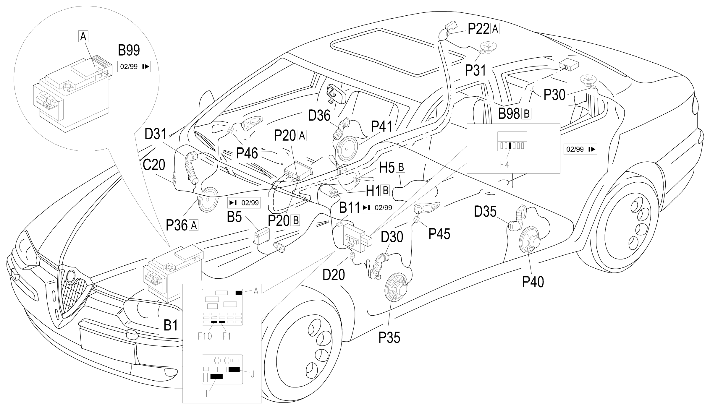
Parts & tools for this job Staging For 1997 Alfa Romeo 156
- TOOLDigital multimeterSearch: automotive digital multimeter
- PARTAssorted fuse kitSearch: car fuse assortment kit
- TOOLWire crimper and connector kitSearch: wire crimper connector kit
Links open Amazon search results in a new tab. As an Amazon Associate I earn from qualifying purchases.