
E4020 Tachometer (Selespeed)
- Make
- Alfa Romeo
- Model
- 156 Factory Service Manual
- Year
- 1997–2002
- Section
- Instruments › E4020 Tachometer (Selespeed)
E4020 Tachometer (Selespeed)
Description
The module includes the electronic rev counter and a series of warning lights.
The engine management unit (specific to each version) produces an rpm signal. The gauge display is produced by an electronic circuit inside the module.
The following warning lights are contained in this module:
- left turn signals
- right turn signals
- recharging
- minimum oil pressure
- injection system failure
- light failure (check)
- main beam headlamps
- side lights/dipped beams
- rear fog lamps
- fog lights
- automatic transmission failure
The rev counter module also contains the check device for the exterior lights which controls the circuits for the side and number plate lights, the rear fog lamps and the brake lights.
The operation of the warning lights which are not included in other functions are illustrated; the others are described and illustrated in the diagrams relating to the components to which they refer.
The rev counter operates when the ignition is switched ON.
In the "night" conditions (side lights on), the brightness can be adjusted to three levels by an external button. ( Wiring diagram E2530 INSTRUMENT LIGHTING ).
Description of operation
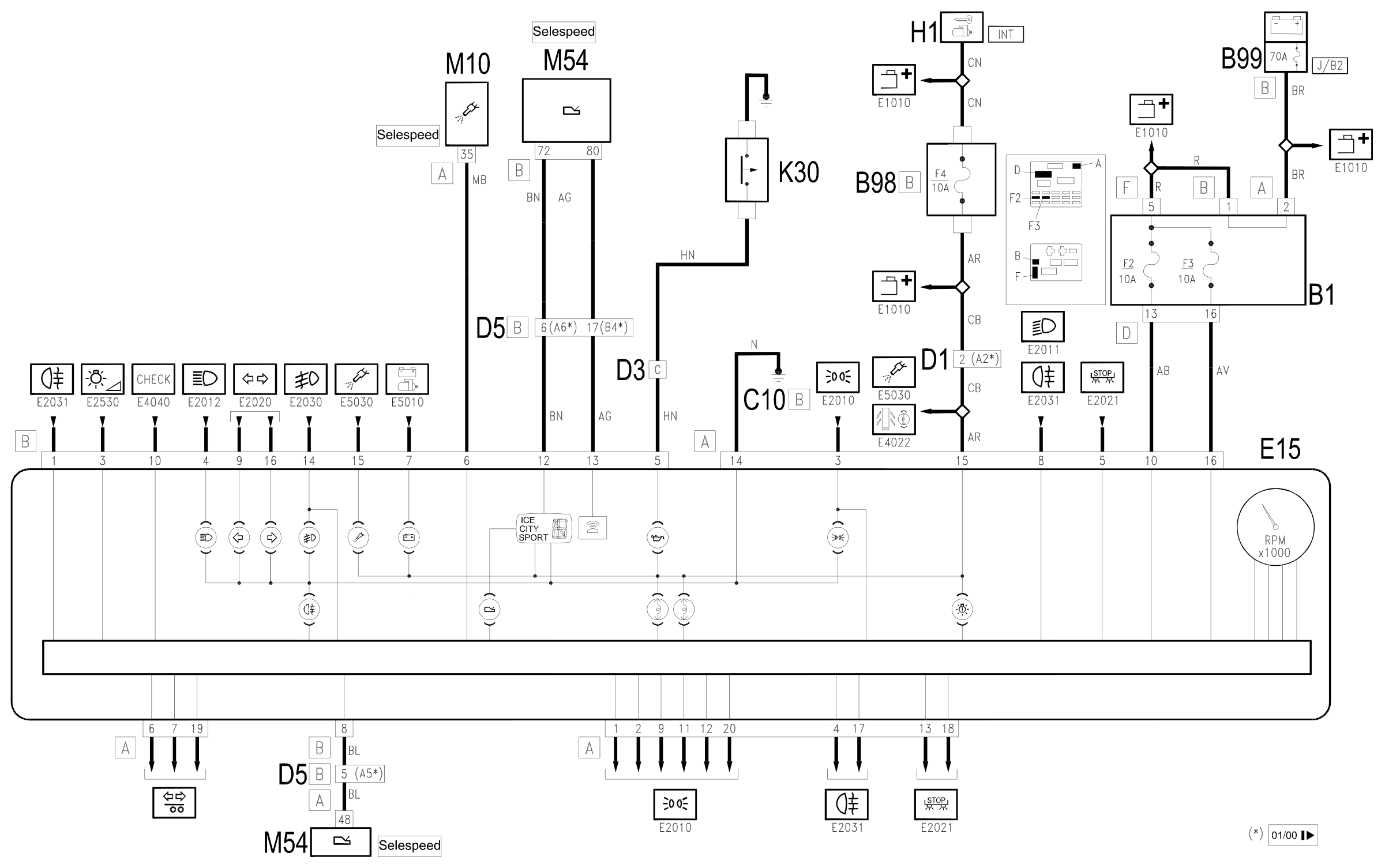
The supply for the rev counter module E15 reaches pins 10 and 16 of connector A directly from the battery. (maxifuse J/B2 of B99, via fuses F2 and F3 of junction unit B1; this supply is also used by the check device for the external lights ( Wiring diagram E2010 SIDE LIGHTS / NUMBER PLATE , Wiring diagram E2021 STOP LIGHT , Wiring diagram E2031 REAR FOG LAMP ).
The rev counter module E15 also receives a supply controlled by the ignition (INT) at pin 15 of connector B from the line protected by fuse F4 of the additional fuse box B98B. Pin 14 of connector B is earthed.
The engine rpm signal, which is different for each engine type, comes from the engine management control unit M10 to pin 6 of connector B.
Insufficient engine oil pressure is signalled at pin 5 of connector B of module E15 by the earth signal coming from sensor K30.
In particular, for the SELESPEED version, the line - pin 12 of connector B of module E15 - connecting to the gearbox management control unit M54 is used for the instrument's gear indicator display and the "automatic transmission fault" warning light.
The control for the buzzer, located in the instrument E15, reaches pin 13 of connector B of the module E15.
The SELESPEED M54 control unit also receives an engine rpm signal, coming from pin 8 of connector B of module E15.
For all the other warning lights, refer to the diagrams relating to the components to which they refer.
Wiring diagram
Components
| Code | Component | See |
|---|---|---|
| B01 | Junction unit | description 5505A |
| B05 | MAXI FUSE-1 box | |
| B11 | Controls lighting fuse | |
| B98 | Supplementary fuse box | description 5505A |
| B99 | Maxifuse box on battery | |
| C10 | Front left earth | description 5505A |
| D01 | Front / dashboard connection | |
| D03 | Front / battery connection | |
| D04 | Front/engine connection | |
| D05 | Front / ABS couping | |
| E15 | Rev counter | description 5560B |
| H01 | Ignition switch | description 5520A |
| K30 | Engine oil pressure sensor (switch) | description 1084A |
| M10 | Engine management ECU | |
| M10 | Engine management control unit | description 1056B |
| M10 | Engine management control unit | description 1060G |
| M54 | Selespeed transmission control unit | description 2127E |
| M55 | Automatic transmission control unit | description 2135B |
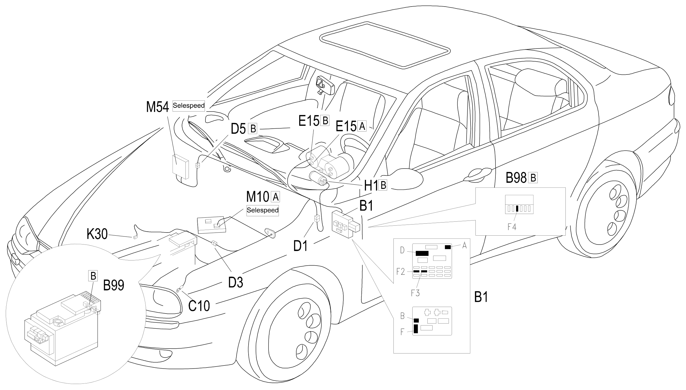
Component location
Parts & tools for this job Staging For 1997 Alfa Romeo 156
- TOOLDigital multimeterSearch: automotive digital multimeter
- PARTAssorted fuse kitSearch: car fuse assortment kit
- TOOLWire crimper and connector kitSearch: wire crimper connector kit
Links open Amazon search results in a new tab. As an Amazon Associate I earn from qualifying purchases.