
E3080 Headlamp geometry adjustment
- Make
- Alfa Romeo
- Model
- 147 Factory Service Manual
- Year
- 2000–2002
- Section
- Electrical activation devices › E3080 Headlamp geometry adjustment
E3080 Headlamp geometry adjustment
Description
The headlamp beam orientation in accordance with the load is adjusted via the adjustment device located directly in the headlamps; it tilts them as appropriate in order to lower the light beam if the vehicle is particularly laden, and raises it when the load decreases.
Two buttons on the panel beside the steering wheel allow the headlamps to be orientated from 0 to 3:
- position 0 - one or two persons on the front seats, full fuel tank, car fully equipped and in running order;
- position 1 - five persons;
- position 2 - five persons with luggage compartment full (about 50 kg);
- position 3 - driver and 300 kg load, all stowed in boot.
The set value is memorised and displayed on the instrument panel.
The control logic described above is managed directly by the instrument panel node.
The device is enabled only when the dipped beam headlamps are on.
The relay which controls the switching on of the dipped beam headlamps Wiring diagram E2011 DIPPED HEADLAMPS also supplies the adjustment motors built into the headlamps; this relay for switching on the dipped beam headlamps is managed by the Body Computer: the relay is energized by enablement signals of ignition on (INT) and the stalk unit dipped beam control.
Description of operation
The dipped beam activation signal is sent to pin 4 of connector D of the Body Computer M1 from the stalk unit H5.
The Body Computer M1 controls the supply to the dipped beam headlamps, sending an earth signal to the unit under the dashboard B2 - from pin 8 of connector F of M1 - which energizes the relay T1; this supplies the dipped beam headlamps and gives enablement to the headlamp adjustment motors F10 (left) and F11 (right).
The headlamp adjustment control, located in the unit H10, sends a control signal - when the relevant buttons are pressed - to the instrument panel E50 - pin 11 of connector B: the internal logic of E50 then sends the actual control signal to the motors, from pin 5 of connector A, while pin 6 of connector A receives the enablement signal (dipped beam lights on).
Wiring diagram
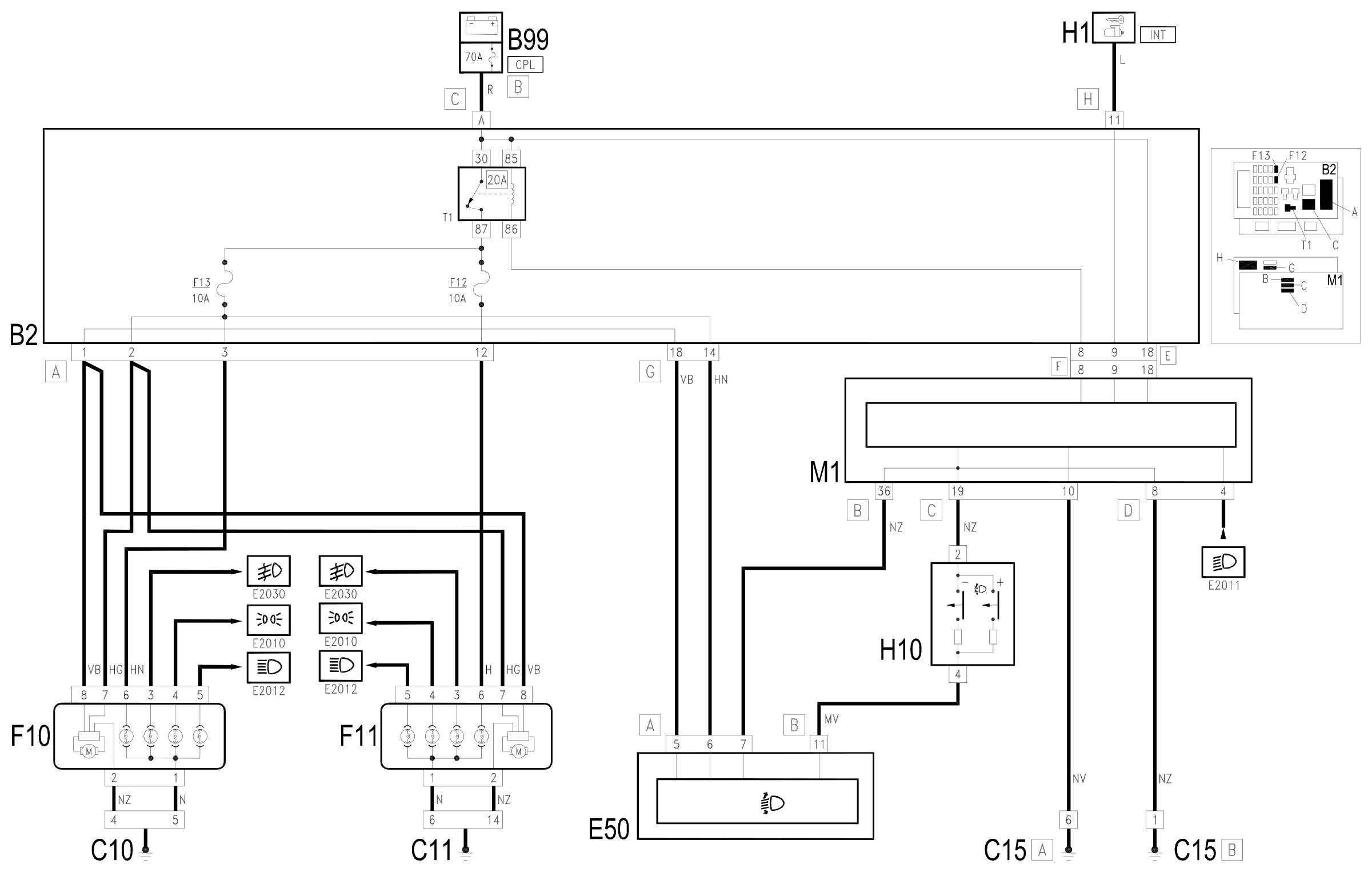
Components
| Code | Component | See |
|---|---|---|
| B02 | Junction unit under dashboard | description 5505A |
| B99 | Maxifuse box on battery | description 5530B |
| C10 | Front left earth | |
| C11 | Right front earth | |
| C15 | Facia earth, driver's side | |
| E50 | Instrument panel | description 5560B |
| F10 | Left headlamp | description 5540B |
| F11 | Right headlamp | description 5540B |
| H01 | Ignition switch | description 5520A |
| H10 | Controls for headlamp alignment, instrument lighting adjustment, milometer zeroing | description 5560B |
| M01 | Body computer | description 5505A |
Component location
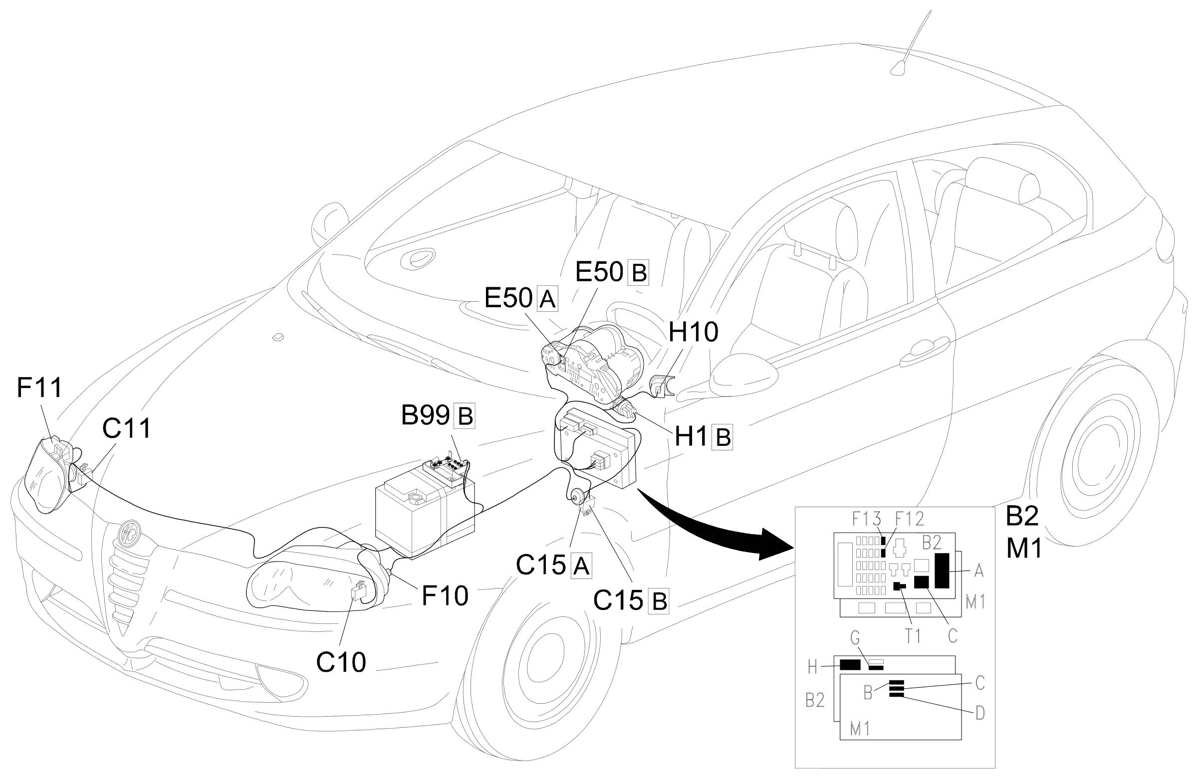
Parts & tools for this job Staging For 2000 Alfa Romeo 147
- PARTReplacement bulbsSearch: Alfa Romeo 147 2000 bulbs
- TOOLDigital multimeterSearch: automotive digital multimeter
Links open Amazon search results in a new tab. As an Amazon Associate I earn from qualifying purchases.