
TIMING CHAIN AND SPROCKETS (page 3 of 4)
- Make
- Land Rover
- Model
- Defender TD5 Defender
12
ENGINE
28
OVERHAUL
Inspection
1. Clean all components.
2. Check condition of timing chain running surfaces
on adjustable and fixed guides.
CAUTION: Adjustable guide fitted to
Engine Serial No. Prefixes 15P to 19P may
be fitted to Engine Serial No. Prefixes 10P
to 14P provided that timing chain tensioner having
a YELLOW colour coded body is also fitted.
3. Check timing chains and sprockets for signs of
wear.
CAUTION: Timing chains and sprockets
fitted to Engine Serial No. Prefixes 15P to
19P may be fitted to Engine Serial No.
Prefixes 10P to 14P as an assembly only, oil pump
sprockets are interchangeable. Timing chains
fitted to Engine Serial No. Prefixes 15P to 19P
have BRONZE coloured timing links.
4. Check that drilling in timing chain lubrication jet
is clear.
5. Clean oil seal recess in timing cover and oil seal
running surface on crankshaft.
6. Remove all traces of sealant from mating faces
of timing cover and cylinder block using suitable
solvent.
CAUTION: Do not use metal scrapers.
7. Ensure bolt and dowel holes are clean and dry.
8. Clean oil pump sprocket bolt threads.
Refit
1. Fit timing chain lubrication jet.
2. Fit bolt securing lubrication jet and tighten to 10
Nm (7 lbf.ft).
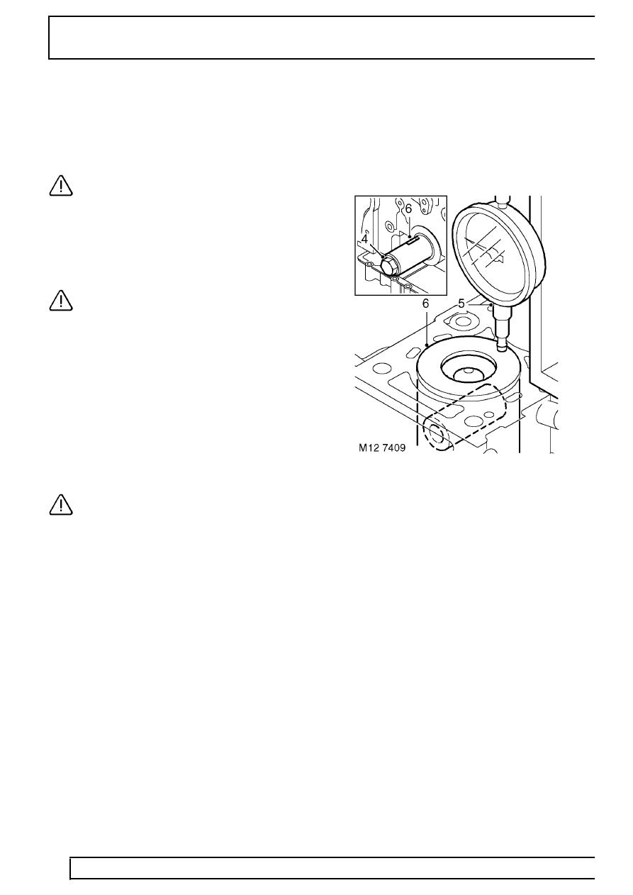
3. If crankshaft has been rotated, check that No. 1
piston is at TDC using the following procedures:
4. Temporarily fit and lightly tighten a new
crankshaft pulley bolt.
5. Assemble a magnetic base DTI to cylinder block
top face, position stylus to cylinder block top face
and zero gauge.
6. Using crankshaft pulley bolt, rotate crankshaft
clockwise until No. 1 piston is at top of its stroke
and Woodruff key slot in crankshaft is at 12
o’clock position.
7. Position stylus of DTI to No. 1 piston crown and
rotate crankshaft until highest reading is
indicated on DTI.
8. Check that Woodruff key slot in crankshaft is still
at 12 o’clock position indicating No. 1 piston is at
TDC firing.
9. Remove DTI.
Parts & tools for this job Staging For Land Rover Defender
- PARTTiming belt kitSearch: Land Rover Defender timing belt kit
- TOOLEngine timing tool setSearch: Land Rover engine timing tool set
- TOOLTorque wrenchSearch: 3/8 inch torque wrench
Links open Amazon search results in a new tab. As an Amazon Associate I earn from qualifying purchases.