
PUMP - OIL (page 2 of 3)
- Make
- Land Rover
- Model
- Defender TD5 Defender
12
ENGINE
24
OVERHAUL
Inspection
CAUTION: Inspection/overhaul procedures
for the oil pump are limited to carrying out
dimensional checks. In the event of wear
or damage being found, a replacement pump and
stiffener plate assembly must be fitted.
Oil pump
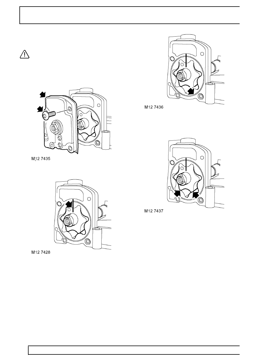
1. Remove and discard 5 screws securing cover to
oil pump, remove cover.
2. Using a felt tipped pen, make suitable alignment
marks between inner and outer rotors and pump
body.
3. Remove inner and outer rotors.
4. Check rotors, cover and pump body for signs of
scoring and wear.
5. Fit rotors ensuring that reference marks are
aligned and identification mark on inner rotor is
facing outwards.
6. Using feeler gauges, check pump body to outer
rotor clearance:
Pump body to outer rotor clearance = 0.295
to 0.375 mm (0.012 to 0.015 in)
7. Using feeler gauges, check clearance of inner to
outer rotor in 2 positions, both clearances must
be within limit given:
Inner to outer rotor clearance = 0.13 mm (0.05
in)
Parts & tools for this job Staging For Land Rover Defender
- PARTOil filterSearch: Land Rover Defender oil filter
- TOOLOil filter wrenchSearch: oil filter wrench
- FLUIDEngine oilSearch: Land Rover Defender engine oil
Links open Amazon search results in a new tab. As an Amazon Associate I earn from qualifying purchases.