
ENGINE AND ANCILLARIES (page 5 of 5)
- Make
- Land Rover
- Model
- Defender TD5 Defender
12
ENGINE
18
REPAIR
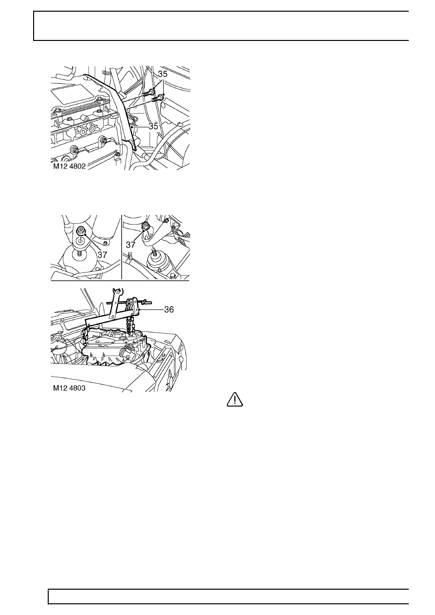
35. Remove 2 bolts and remove acoustic cover from
rear of cylinder head.
36. Fit LRT-12-138 to suitable lifting chains and
connect to lifting eyes on engine.
37. Remove 2 nuts from RH and LH front engine
mountings.
38. Fit trolley jack to support gearbox.
39. With assistance raise chains and remove engine
from vehicle.
Refit
40. With assistance, raise engine from bench and
position in vehicle.
41. With assistance, align engine to gearbox input
shaft.
42. Position 2 upper bolts securing gearbox housing
to engine and tighten to 50 Nm (37 lbf.ft).
43. Lower engine onto mountings and tighten nuts to
85 Nm (63 lbf.ft).
44. Remove LRT-12-138 from engine.
45. Fit and tighten bolt securing engine closing panel
to gearbox.
46. Raise vehicle on ramp.
47. Fit bolts securing gearbox housing to engine and
tighten to 50 Nm (37 lbf.ft).
48. Lower ramp.
49. Fit acoustic cover to rear of cylinder head and
tighten bolts.
50. Position coolant hose to engine oil cooler and
secure clip.
51. Position PAS pump and tighten bolts to 25 Nm
(18 lbf.ft).
52. Position PAS pulley and tighten bolts to 25 Nm
(18 lbf.ft).
53. Position A/C compressor and tighten bolts to 25
Nm (18 lbf.ft).
54. Route engine harness beneath inlet manifold
and connect multiplugs to oil pressure switch,
A/C compressor, and ECT sensor.
55. Fit and tighten bolts securing engine harness to
camshaft carrier.
56. Connect multiplug to alternator.
57. Connect battery lead to alternator and tighten
nut.
58. Clean CKP sensor and mating face.
CAUTION: If originally fitted:- Fit spacer to
CKP sensor.
59. Using a new ’O’ ring, fit CKP sensor, tighten bolt
to 10 Nm (7 lbf.ft) .
60. Connect CKP sensor multiplug.
61. Connect multiplugs to EGR solenoid, inlet
manifold sensor, injector harness, fuel
temperature sensor and CKP sensor.
62. Connect glow plug leads.
63. Connect multiplug to condensor cooling fan.
64. Connect vacuum hose to EGR valve.
65. Connect EGR vacuum hose to vacuum pipe.
66. Position pipe to vacuum pump and secure pipe
to acoustic cover clips.
67. Position fuel cooler. Apply Loctite 242 to bolts
and tighten to 18 Nm (13 lbf.ft).
68. Disconnect fuel hose from connector block and
connect to fuel cooler.
69. Connect fuel hoses to fuel cooler and connector
block on cylinder head.
Parts & tools for this job Staging For Land Rover Defender
- PARTEngine gasket setSearch: Land Rover Defender engine gasket set
- TOOLTorque wrenchSearch: 3/8 inch torque wrench
- TOOLFeeler gauge setSearch: feeler gauge set
Links open Amazon search results in a new tab. As an Amazon Associate I earn from qualifying purchases.