
Thermostat unit - r.r.
- Make
- Lancia
- Model
- Thesis Factory Service Manual
- Year
- 2002–2009
- Section
- Engine cooling › Thermostat unit - r.r.
THERMOSTAT UNIT - R.R.
Removing
- Position the vehicle on a lift.
See in Op. 1016A10
- Raise the lift.
See in Op. 7055B54 PROTECTION/GUARD under engine - R.R.
See in Op. 1048A50
See in Op. 1048A21
- Have a suitable container for collecting the coolant ready.
- Disconnect the lower pipe from the radiator and drain the engine cooling system.
- Remove the container for collecting the coolant.
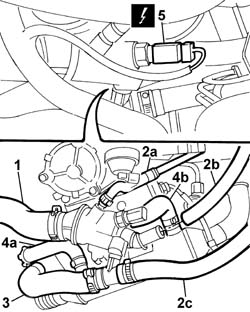
1. Disconnect the upper radiator pipe from the thermostat.
2. Disconnect the recirculation pipe (2a) to the reservoir and the two heater supply and return pipes (2b) and (2c) from the thermostat.
3. Disconnect the pipe from the thermostat and from the EGR supply pipe, then remove it.
4. Remove the supply pipe from the thermostat to the water pump rigid filler pipe.
5. Disconnect the pipe (5a) from the exhaust gas supply pipe to the pump rigid inlet pipe and the pipe (5b) from the thermostat to the rigid supply section to the engine oil heat exchanger.
6. Disconnect the electrical connection for the coolant temperature sensor.
| Description | Connector | |
|---|---|---|
| 6 | I.E. engine temperature sensor | K045 |
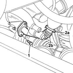
1. Undo the bolts fixing the EGR supply pipe to the exhaust pipe.
2. Disconnect the pipe from the band (2a) connected to the centre section under the thermostat and remove the front section of the EGR supply pipe.
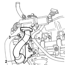
1. Undo the bolts fixing the exhaust gas supply to the EGR solenoid valve.
2. Disconnect the pipe from the band (2a) connected to the centre section under the thermostat and remove the rear section of the EGR supply pipe.
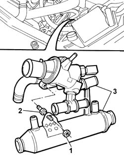
1. Undo the bolts fixing the exhaust supply supply pipe mounting bracket to the cylinder head.
2. Undo the nut fixing the exhaust gas supply pipe to the thermostat stud.
3. Undo the bolts fixing the thermostat to the cylinder head.
4. Remove the thermostat unit together with the centre section of the EGR exhast gas supply pipe.
Refitting
- Fit the thermostat/EGR exhaust gas supply pipe centre section.
- Tighten the thermostat fixing bolts to torque.
| Value - daNm | Fastening | Component | Ø | |
|---|---|---|---|---|
| 2.5 | Bolt | THERMOSTAT | M8 |
- Tighten the nut fixing the exhaust gas supply pipe to the thermostat stud/bolt.
- Tighten the bolts fixing the exhaust supply supply pipe to the cylinder head.
- Fit the front section and the rear section of the exhaust gas supply pipe to the centre section, securing it using the bands.
- Tighten the bolts fixing the front sectio nof the exhaust gas supply pipe to the exhaust manifold.
| Value - daNm | Fastening | Component | Ø | |
|---|---|---|---|---|
| 2.5 | Bolt | EGR VALVE PIPE | M8 |
- Tighten the bolts fixing the rear section of the exhaust pipe to the EGR valve.
| Value - daNm | Fastening | Component | Ø | |
|---|---|---|---|---|
| 2.5 | Bolt | EGR VALVE PIPE | M8 |
- Connect the electrical connection for the coolant temperature sensor.
- Connect the flexible rubber pipes disconnected from the thermostat.
See in Op. 1048A21
See in Op. 1048A50
- Finish with the lift.
See in Op. 1016A10
See in Op. 0010T20 Engine REFRIGERANT FLUID - Change
See in Op. 7055B54 PROTECTION/GUARD under engine - R.R.
- Remove the vehicle from the lift.
Removing
- Position the vehicle on a lift.
- Make sure that the ignition key is in the OFF position, then disconnect the negative battery terminal.
See in Op. 7040D50 ENGINE COMPARTMENT UPPER SOUND INSULATION SHIELD - R.R.
See in Op. 7055B54 PROTECTION/GUARD under engine - R.R.
See in Op. 1048A28 vacuum air circuit resonator pipe - r+r
See in Op. 1048A50 air inlet pipe to turbocharger - r + r
See in Op. 1048A21 AIR INLET HOSE FROM INTAKE TO FILTER - R.R.
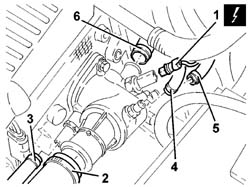
1. Disconnect the electrical connection from the engine coolant temperature sensor.
| Description | Connector | |
|---|---|---|
| 1 | I.E. engine temperature sensor | K045 |
2. Disconnect the upper radiator coolant inlet hose from the thermostat unit.
Collect the coolant that comes out in a suitable container.
3. Disconnect the coolant supply pipe to the engine oil heat exchanger from the thermostat unit.
4. Disconnect the supply pipe to the engine coolant tank from the thermostat unit.
5. Disconnect the supply pipe to the heater from the thermostat unit.
6. Disconnect the return pipe to the water pump from the thermostat unit.
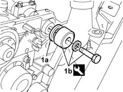
1. Undo the bolts (1a) and remove the thermostat unit (1b) complete with O-ring (1c).
Refitting
- Position the thermostat unit, complete with O-ring, in its housing and secure it tightening the bolts to the recommended torque.
| Value - daNm | Fastening | Component | Ø | |
|---|---|---|---|---|
| 2.5 | Bolt | THERMOSTAT | M8 |
- Connect the water pump return pipe to the thermostat unit.
- Connect the heater supply pipe to the thermostat unit.
- Connect the engine coolant tank supply pipe to the thermostat unit.
- Connect the engine oil heat exchanger coolant supply pipe to the thermostat unit.
- Connect the upper radiator coolant inlet hose to the thermostat unit.
- Connect the electrical connection to the engine coolant temperature sensor.
| Description | Connector | |
|---|---|---|
| I.E. engine temperature sensor | K045 |
See in Op. 1048A28 vacuum air circuit resonator pipe - r+r
See in Op. 1048A50 air inlet pipe to turbocharger - r + r
See in Op. 1048A21 AIR INLET HOSE FROM INTAKE TO FILTER - R.R.
See in Op. 7055B54 PROTECTION/GUARD under engine - R.R.
See in Op. 0010T20 Engine REFRIGERANT FLUID - Change
See in Op. 7040D50 ENGINE COMPARTMENT UPPER SOUND INSULATION SHIELD - R.R.
- Connect the negative battery lead.
- Remove the vehicle from the lift.
Removing
See in Op. 7055B54 PROTECTION/GUARD under engine - R.R.
- Lower the vehicle.
See in Op. 7040D50 ENGINE COMPARTMENT UPPER SOUND INSULATION SHIELD - R.R.
See in Op. 1016A10 SOUND-PROOFING COVER - R.R.
See in Op. 1048B44 RIGID air supply PIPE from heat exchanger to intake manifold - R.R.
See in Op. 1048A56 UPPER RESONATOR - R.R.
See in Op. 1048A50 air inlet pipe to turbocharger - r + r
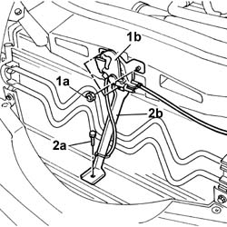
1. Undo the fixing nuts (1a) and remove the bonnet lock (1b) from the housing in the crossmember.
2. Undo the lower nut (2a) and remove the lock reinforcement bracket (2b).
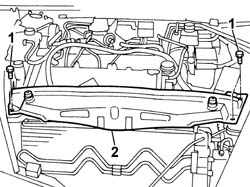
1. Undo the retaining bolts.
2. Remove the upper front crossmember.
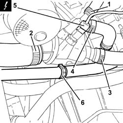
1. Loosen the coolar and disconnect the coolant return pipe from the engine coolant reservoir, thermostat side.
2. Loosen the collar and disconnect the upper coolant input sleeve to the radiator, thermostat side.
3. Loosen the collar and disconnec the coolant delivery pipe to the climate control system heater, thermostat side.
4. Loosen the collar and disconnect the coolant delivery pipe to the coolant/exhaust gas heat exchanger for the EGR system, thermostat side.
Collect the coolant that comes out in a suitable container..
5. Disconnect the electrical connection from the engine coolant temperature sensor.
| Description | Connector | |
|---|---|---|
| 5 | Engine coolant temperature sensor/sender unit | K036 |
6. Open the collar and release the coolant return pipe from the heater.
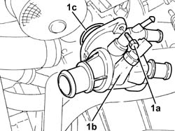
1. Undo the bolts (1a) and remove the thermostat (1b) complete with O-ring (1c).
Refitting
- Fit the vacuum unit complete with o-ringand fasten it by tightening the bolts to the recommended torque.
- Connect the electrical connection to the engine coolant temperature sensor.
| Description | Connector | |
|---|---|---|
| Engine coolant temperature sensor/sender unit | K036 |
- Connect the coolant delivery pipe to the coolant/exhaust gas heat exchanger for the EGR system, thermostat side and tighten the collar.
- Connect the coolant delivery pipe to the climate control system heater, thermostat side, and tighten the band.
- Connect the upper coolant input sleeve to the radiator, thermostat side, and tighten the band.
- Connect the coolant return pipe from the engine coolant reservoir to the coolant reservoir, thermostat side, and tighten the collar.
- Fit the upper front crossmember and tighten the fixing bolts to torque.
| Value - daNm | Fastening | Component | Ø | |
|---|---|---|---|---|
| 0.6 | Bolts | FRONT WING CROSSMEMBER HEADLAMP HOUSINGS | M6 |
- Fit the bonnet lid lock complete with bracket and tighten the nuts fixing it to the upper crossmember and to the lower crossmember.
See in Op. 1048A50 air inlet pipe to turbocharger - r + r
See in Op. 1048A56 UPPER RESONATOR - R.R.
See in Op. 1048B44 RIGID air supply PIPE from heat exchanger to intake manifold - R.R.
See in Op. 1016A10 SOUND-PROOFING COVER - R.R.
See in Op. 7040D50 ENGINE COMPARTMENT UPPER SOUND INSULATION SHIELD - R.R.
- Raise the vehicle.
Parts & tools for this job Staging For 2002 Lancia Thesis
- FLUIDCoolantSearch: Lancia coolant antifreeze
- PARTThermostatSearch: Lancia Thesis 2002 thermostat
- TOOLCooling system pressure testerSearch: cooling system pressure tester
Links open Amazon search results in a new tab. As an Amazon Associate I earn from qualifying purchases.