
Description of components
- Make
- Lancia
- Model
- Thesis Factory Service Manual
- Year
- 2002–2009
- Section
- Engine cooling › Description of components
DESCRIPTION OF COMPONENTS
ENGINE COOLANT RESERVOIR - R.R.
Specifications
Function
In addition to supplying the circuit, the coolant reservoir absorbs the variations in the volume of the coolant as the temperature of the engine varies and condenses the coolant vapours thereby avoiding the need for refilling.
A special calibrated valve in the pressurised cap assures the following:
- escape of air from the circuit collected by the pipe coming from the thermostat
- air intake when the circuit contains a vacuum (due to engine cooling).
The maximum pressure reached by the engine cooling circuit is 1.4 bar.
ENGINE COOLING RADIATOR
Composition
Structure
It consists of a radiant mass and two side tanks for the intake and outlet of coolant.
The radiator pipes and fins are aluminium, the tanks are plastic.
WATER PUMP
Specifications
Type
This is a centrifugal vane pump with an aluminium alloy casng and phenolic resin impeller.
Secured to the engine crankcase and driven directly by timing belt.
THERMOSTAT
Operation
General remarks
Fitted to the rear of the cylinder head and performs the function of maintaining the engine at optimum temperature:
- with the temperature %lt; 80 ± 2°C the termostatic valve (closed) directs the fluid directly to the pump
- with the temperature %gt; 80 ± 2'C the thermostatic valve (open) directs the coolant towards the radiator.
The engine coolant temperature sensor is fitted on the thermostat and is connected to the injection control unit and the instrument panel.
(See assembly ) 1060G
FANS
Specifications
Function
The two speed cooling fans make it possible to increase the capacity dissipate heat from the radiator and/or air conditioning system condenser.
They are controlled directly by the injection control unit in accordance with a specific operating logic [DF 1060].
Fan control
According to coolant temperature and coolant pressure in the air conditioning system, the engine control node communicates with the fan control interface to provide enablement for:
- fan activation at first or second speeds.
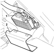
- 1 Engine coolant temperature multifunction control unit
- 2 Multifunction control unit cover
Engine coolant temperature control
The engine control node with coolant temperature higher than 105° C.:
- reduces injected fuel quantity (reduces engine power)
- controls the cooling fan via the fan control interface
- turns on the coolant warning light on the instrument panel.
ENGINE COOLANT RESERVOIR - R.R.
Specifications
Function
In addition to supplying the circuit, the coolant reservoir absorbs fluctuations in coolant volume as engine temperature changes.
A special calibrated valve in the pressurised plug allows:
- the emergence of air from the collection circuit through a pipe leading from the thermostat.
- air intake when the circuit contains a vacuum (due to engine cooling).
ENGINE COOLING RADIATOR
Composition
Structure
This consists of a radiant mass and a side reservoir for coolant intake and outlet.
The radiant mass pipes and fins aer in aluminium. The reservoir is plastic.
WATER PUMP
Specifications
Type
This is centrifugal, vane type with an aluminium alloy pump casing and phenolic resin impeller.
Secured to the engine crankcase and driven directly by timing belt.
THERMOSTAT
Operation
General remarks
Fitted to the rear of the cylinder head and performs the function of maintaining the engine at optimum temperature:
- with temperature < 83 +/- 2°C the thermostat valve (closed) deviates fluid directly toward the pump.
- with temperature > 83 +/- 2°C the thermostat valve (open) deviates coolant directly toward the radiator.
The engine coolant temperature sensor fitted to the thermostat is connected to the injection control unit and control panel [DF 1056B].
FAN
Specifications
Function
The two-speed cooling fan increase the heat dissipation capacity of the radiator and/or air conditioning system condenser.
They are controlled directly by the injection control unit in accordance with a specific operating strategy [DF 1056B].
Fan control
According to coolant temperature and coolant pressure in the air conditioning system, the engine control node communicates with the fan control interface to provide enablement for:
- fan activation at first or second speeds.
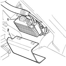
- 1 Engine coolant temperature multifunction control unit
- 2 Multifunction control unit cover
Engine coolant temperature control
The engine control node with coolant temperature higher than 105° C.:
- reduces injected fuel quantity (reduces engine power)
- controls the cooling fan via the fan control interface
- turns on the coolant warning light on the instrument panel
WATER PUMP
Specifications
Type
This is a centrifugal vane pump with an aluminium alloy casng and phenolic resin impeller.
Secured to the engine crankcase and driven directly by timing belt.
THERMOSTAT
Operation
General remarks
Fitted to the rear of the cylinder head and performs the function of maintaining the engine at optimum temperature:
- with the temperature %lt; 80 ± 2°C the termostatic valve (closed) directs the fluid directly to the pump
- with the temperature %gt 80 ± 2'C the thermostatic valve (open) directs the coolant towards the radiator.
The engine coolant temperature sensor is fitted on the thermostat and is connected to the injection control unit and the instrument panel.
(See assembly ) 1060G
FANS
Specifications
Function
The two speed cooling fans make it possible to increase the capacity dissipate heat from the radiator and/or air conditioning system condenser.
They are controlled directly by the injection control unit in accordance with a specific operating logic [DF 1060].
Fan control
According to coolant temperature and coolant pressure in the air conditioning system, the engine control node communicates with the fan control interface to provide enablement for:
- fan activation at first or second speeds.
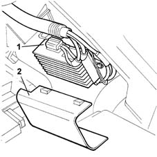
- 1 Engine coolant temperature multifunction control unit
- 2 Multifunction control unit cover
Engine coolant temperature control
The engine control node with coolant temperature higher than 105° C.:
- reduces injected fuel quantity (reduces engine power)
- controls the cooling fan via the fan control interface
- turns on the coolant warning light on the instrument panel.
ENGINE COOLANT RESERVOIR - R.R.
Specifications
Function
ENGINE COOLING RADIATOR
Composition
Structure
WATER PUMP
Specifications
Type
THERMOSTAT
Operation
General remarks
FAN
Specifications
Function
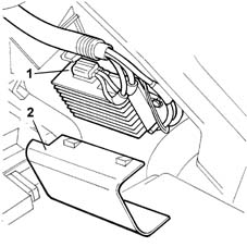
Engine coolant temperature control.
ENGINE COOLANT RESERVOIR - R.R.
Specifications
Function
In addition to supplying the circuit, the coolant reservoir absorbs the variations in the volume of the coolant as the temperature of the engine varies.
The maximum pressure reached by the engine cooling circuit is 1.4 bar.
A special calibrated valve in the pressurised cap assures the following:
- emergence of air from the circuit collected by the pipe leading from thermostat.
- air intake when the circuit contains a vacuum (due to engine cooling).
ENGINE COOLING RADIATOR
Composition
Structure
This consists of a radiant mass and a side tank for coolant intake and outlet.
The radiator pipes and fins are aluminium, the tanks are plastic.
WATER PUMP
Specifications
Type
This is a centrifugal vane pump with an aluminium alloy casng and phenolic resin impeller.
It is secured to the crankcase and crankshaft-driven via a poly-V belt.
THERMOSTAT
Operation
General remarks
This is fitted to the gearbox end cylinder head and maintains the engine at optimum temperature:
- with temperature %lt; 87 ± 2°C, the thermostat valve (closed) directs fluid to the pump.
- with temperature %lt; 87 ± 2°C, the thermostat valve (open) directs fluid to the radiator.
The engine coolant sensor fitted to the thermostat is connected to the injection control unit and control panel [DF 1056].
FAN
Specifications
Function
The two-speed cooling fan increases the heat dissipation capacity of the radiator and/or air conditioning condenser.
They are driven directly by the injection control unit on the basis of a specific operating strategy [DF 1056].
Fan control
According to coolant temperature and coolant pressure in the air conditioning system, the engine control node communicates with the fan control interface to provide enablement for:
- fan activation at first or second speeds.
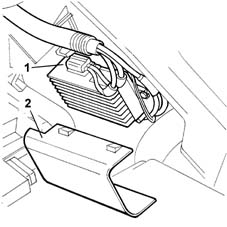
- 1 Engine coolant temperature multifunction control unit
- 2 Multifunction control unit cover
Engine coolant temperature control
The engine control node with coolant temperature higher than 105° C.:
- reduces injected fuel quantity (reduces engine power)
- controls the cooling fans via the fan control interface
- turns on the coolant warning light on the instrument panel.
Parts & tools for this job Staging For 2002 Lancia Thesis
- PARTEngine gasket setSearch: Lancia Thesis 2002 engine gasket set
- TOOLTorque wrenchSearch: 3/8 inch torque wrench
- TOOLFeeler gauge setSearch: feeler gauge set
Links open Amazon search results in a new tab. As an Amazon Associate I earn from qualifying purchases.