
SINGLE CAMSHAFT HOUSING - REPLACE gasket
- Make
- Lancia
- Model
- Thesis Factory Service Manual
- Year
- 2002–2009
- Section
- Cylinder head – s › SINGLE CAMSHAFT HOUSING - REPLACE gasket
SINGLE CAMSHAFT HOUSING - REPLACE gasket
Removing
See in Op. 7055B54 PROTECTION/GUARD under engine - R.R.
See in Op. 4450B04 Right FRONT WHEEL (one) - R.R.
See in Op. 7055B42 FRONT WHEEL ARCH LINER (one), left or right - R.R.
See in Op. 7055B64 Engine compartment DUST SEAL in front wheel arch (one), left or right - R.R.
See in Op. 1016A10 SOUND-PROOFING COVER - R.R.
See in Op. 7040D50 ENGINE COMPARTMENT UPPER SOUND INSULATION SHIELD - R.R.
See in Op. 1048B44 RIGID air supply PIPE from heat exchanger to intake manifold - R.R.
See in Op. 1048A56 UPPER RESONATOR - R.R.
See in Op. 1092G10 Engine components single drive BELT - R.R.
See in Op. 1092G21 Engine components single belt FIXED TENSIONER - R.R. with belt removed
See in Op. 1092A10 Crankshaft PULLEY - R.R.
See in Op. 1032D12 Timing system protective COVER(S) - R.R.
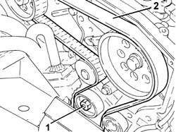
1. Loosen the nut retaining the timing belt moving tensioner.
2. Release and remove the toothed timing drive belt.
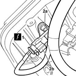
1. Disconnect the electrical connection for the timing sensor.
| Description | Connector | |
|---|---|---|
| 1 | Timing sensor | K047 |
2. Undo the fixing bolt (2a) and remove the sensor (2b) from the housing in the camshaft housing.
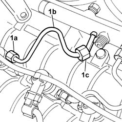
1. Undo the connectors (1a) and (1b) and remove the pipes from the fuel manifold to the injectors (1c).
Use new pipes from the fuel manifold to the injectors when refitting.
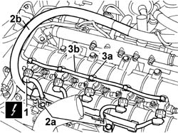
1. Disconnect the electrical connections from the injectors.
| Description | Connector | |
|---|---|---|
| 1 | Injector | N070A |
| Description | Connector | |
|---|---|---|
| 1 | Injector | N070B |
| Description | Connector | |
|---|---|---|
| 1 | Injector | N070C |
| Description | Connector | |
|---|---|---|
| 1 | Injector | N070D |
| Description | Connector | |
|---|---|---|
| 1 | Injector | N070E |
2. Undo the fixing bolts (2a) and release the electrical wiring (2b) moving outside of the work area.
3. Manually push the clips (3a) and disconnect the pipe from the injectors to the fuel recovery manifold (3b), injector side, and move it sideways.
1. Undo the injector bracket retaining nuts.
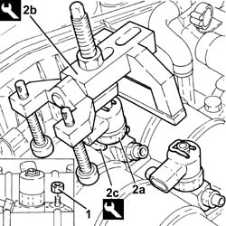
2. Remove the injectors (2a) complete with brackets using the tools (2b) and (2c).
If the injectors are being reused, mark the cylinder to which they belong so that they can be correctly refitted. If new injector(s) is(are) being fitted, it is necessary to:
Start the removal beginning with the injector for cylinder no. 1 and continue with the injectors for cylinders 2, 3, 4 and 5.
| Description | Code | Function | |
|---|---|---|---|
| 2b | Extractor | 1.870.739.000 | Removing injectors |
| Description | Code | Function | |
|---|---|---|---|
| 2b | Extractor | 1.870.897.300 | Removing injectors |
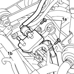
1. Loosen the bolts (1a) fixing the fuel return manifold (1b).
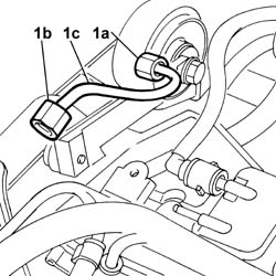
1. Undo the connectors (1a), (1b) and remove the pipe from the pressure pump to the fuel manifold (1c).
Use a new pipe from the pressure pump to the fuel manifold when refitting.
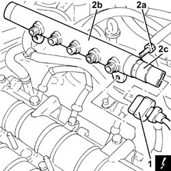
1. Disconnect the electrical connection from the fuel pressure sensor.
| Description | Connector | |
|---|---|---|
| 1 | Fuel pressure sensor | K083 |
2. Undo the bolts (2a) and remove the single fuel manifold pipe (2b) complete with fuel pressure sensor (2c).
1. Disconnect the vacuum pipe from the vacuum unit.
2. Disconnect the pipe from the engine oil filler to the separator.
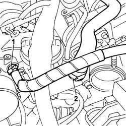
1. Disconnect the electrical wiring from the heater plugs.
| Description | Connector | |
|---|---|---|
| 1 | Heater plugs | A040A |
| Description | Connector | |
|---|---|---|
| 1 | Heater plugs | A040E |
| Description | Connector | |
|---|---|---|
| 1 | Heater plugs | A040D |
| Description | Connector | |
|---|---|---|
| 1 | Heater plugs | A040C |
| Description | Connector | |
|---|---|---|
| 1 | Heater plugs | A040B |
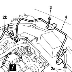
2. Disconnect the flexible sections of the vacuum pipes from the variable geometry solenoid valve (2a) and vacuum reservoir solenoid valve (2b).
3. Undo the retaining bolts.
4. Remove the rigid section of the vacuum pipe.
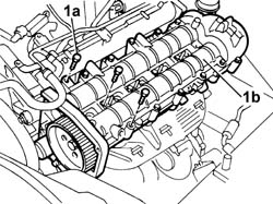
1. Undo the fixing bolts (1a) and (1b) and remove the single camshaft housing (1c).
- Recover the underlying gasket.
Refitting
- Fit a new gasket on the cylinder head.
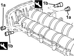
1. Remove the plugs (1a) and fit the camshaft timing tools (1b) on the camshaft housing.
Check that the tools are correctly fitted in the housings in the camshafts.
| Description | Code | Function | |
|---|---|---|---|
| 1b | Templates | 1.870.896.900 | Engine tuning |
- Remove the inlet side camshaft timing tool and tighten the plug.
1. Place the camshaft housing assembly (1a) in position and secure it tightening the bolts (1b) to the recommended torque.
2. Loosen the bolt fixing the exhaust side camshaft pulley.
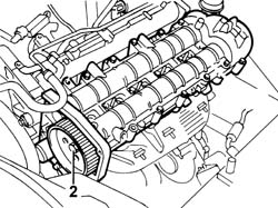
1. Undo the bolt fixing the crankcase front cover shown in the diagram.
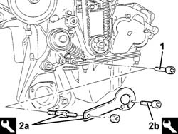
- Fit the timing drive belt on the drive gear, checking that the belt teeth are correctly inserted in the gear grooves.
2. Fit the tool (2a) and fasten it using the calibrated screw (2b).
The crankshaft must be rotated, using small movements, to allow the locating dowel to be fitted on the timing drive pulley.
| Description | Code | Function | |
|---|---|---|---|
| 2a | Template | 1.860.905.000 | Timing belt timing |
| Description | Code | Function | |
|---|---|---|---|
| 2b | Calibrated Screw | 1.860.905.010 | Timing belt timing |
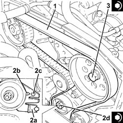
1. Fully fit the toothed timing drive belt.
2. Use a screwdriver for leverage in the opening (2a) until the reference for the tensioner (2b) is aligned with the opening reference (2c) and, in this position, tighten the nut (2d) for the belt tensioner to the recommended torque.
| Value - daNm | Fastening | Component | Ø | |
|---|---|---|---|---|
| 2d | 2.5 | Nut | MOBILE TIMING TENSIONER | M8 |
3. Tighten the bolt fixing the exhaust side camshaft toothed pulley to the recommended torque.
| Value - daNm | Fastening | Component | Ø | |
|---|---|---|---|---|
| 3 | 12 | Bolt | TIMING DRIVEN PULLIES | M12 |
- Remove the timing tools.
| Description | Code | Function | |
|---|---|---|---|
| Templates | 1.870.896.900 | Engine tuning |
| Description | Code | Function | |
|---|---|---|---|
| Template | 1.860.905.000 | Timing belt timing |
| Description | Code | Function | |
|---|---|---|---|
| Calibrated Screw | 1.860.905.010 | Timing belt timing |
- Rotate the crankshaft through two revolutions.
- Check that the timing is correct once again by refitting the timing tools.
Only fit the exhaust camshaft template because the inlet side one is not accessible.
- Check the alignment of the tensioning references on the timing moving tensioner.
- Tighten the bolt fixing the crankcase front cover removed previously.
- Tighten the plug in the camshaft housing for fitting the exhaust side timing tool.
- Connect the pipe from the engine oil filler to the separator.
- Connect the vacuum pipe to the vacuum unit.
- Fit the rigid section of the vacuum pipe.
- Tighten the fixing bolts and connect the flexible sections of the vacuum pipes to the variable geometry solenoid valve and to the vacuum reservoir solenoid valve.
- Connect the electrical wiring to the heater plugs.
| Description | Connector | |
|---|---|---|
| Heater plugs | A040A |
| Description | Connector | |
|---|---|---|
| Heater plugs | A040D |
| Description | Connector | |
|---|---|---|
| Heater plugs | A040E |
| Description | Connector | |
|---|---|---|
| Heater plugs | A040C |
| Description | Connector | |
|---|---|---|
| Heater plugs | A040B |
1. Fit the single fuel manifold pipe (1a) complete with fuel pressure sensor (1b) and secure it tightening the bolts (1c) to the recommended torque.
| Value - daNm | Fastening | Component | Ø | |
|---|---|---|---|---|
| 1c | 2.5 | Bolts | INJECTOR FUEL MANIFOLD (DIESEL) | M8 |
2. Connect the electrical connection to the fuel pressure sensor.
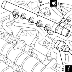
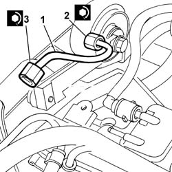
1. Fit a new pipe from the pressure pump to the single fuel manifold and secure it using the connectors without tightening them.
2. Tighten the connector for the pipe from the pressure pump to the single fuel manifold, pump side, to the recommended torque using a spanner.
| Value - daNm | Fastening | Component | Ø | |
|---|---|---|---|---|
| 2 | (pump side) 2.3 | Connector | PRESSURE PUMP LINE TO FUEL MANIFOLD | M14X1.5 |
3. Tighten the connector for the pipe from the pressure pump to the single fuel manifold, fuel manifold side, to the recommended torque using a spanner.
| Value - daNm | Fastening | Component | Ø | |
|---|---|---|---|---|
| 3 | (manifold side) 2.3 | Connector | PRESSURE PUMP LINE TO FUEL MANIFOLD | M14X1.5 |
- Tighten the bolts fixing the fuel return manifold to the recommended torque.
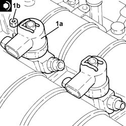
1. Fit the injectors (1a) in their seats complete with brackets and tighten the nuts (1b) to the recommended torque.
Start the refitting beginning with the injector for cylinder no. 5 and continue with the injectors for cylinders 4, 3, 2, and 1.
| Value - daNm | Fastening | Component | Ø | |
|---|---|---|---|---|
| 1b | 3 | Nut | INJECTORS(DIESEL) | M8X1,25 |
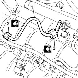
1. Fit the new pipes from the fuel manifold to the injectors and secure them without tightening the connectors.
2. Tighten the connectors for the pipes from the fuel manifold to the injector side injectors to the recommended torque using an ordinary spanner.
| Value - daNm | Fastening | Component | Ø | |
|---|---|---|---|---|
| 2 | (injector side) 2 | Connectors | INJECTOR FUEL MANIFOLD PIPE | M12X1.5 |
3. Tighten the connectors for the pipes from the fuel manifold to the fuel manifold side injectors to the recommended torque using an ordinary spanner.
| Value - daNm | Fastening | Component | Ø | |
|---|---|---|---|---|
| 3 | (manifold side) 2 | Connectors | PIPE FUEL MANIFOLD TO INJECTORS | M12X1.5 |
Clean the threaded seats for the above pipe on the manifold and on the injectors using heptane.
- Connect the pipe from the injectors to the fuel recovery manifold pushing it until the clips can be head clicking.
- Place the electrical wiring in position and tighten the cable duct fixing bolts.
- Connect the electrical connections for the injectors.
| Description | Connector | |
|---|---|---|
| Injector | N070A |
| Description | Connector | |
|---|---|---|
| Injector | N070B |
| Description | Connector | |
|---|---|---|
| Injector | N070E |
| Description | Connector | |
|---|---|---|
| Injector | N070D |
| Description | Connector | |
|---|---|---|
| Injector | N070C |
- Fit the timing sensor and tighten the retaining bolt.
- Connect the electrical connection to the timing sensor.
| Description | Connector | |
|---|---|---|
| Timing sensor | K047 |
See in Op. 1032D12 Timing system protective COVER(S) - R.R.
See in Op. 1092A10 Crankshaft PULLEY - R.R.
See in Op. 1092G21 Engine components single belt FIXED TENSIONER - R.R. with belt removed
See in Op. 1092G10 Engine components single drive BELT - R.R.
See in Op. 1048A56 UPPER RESONATOR - R.R.
See in Op. 1048B44 RIGID air supply PIPE from heat exchanger to intake manifold - R.R.
See in Op. 7040D50 ENGINE COMPARTMENT UPPER SOUND INSULATION SHIELD - R.R.
See in Op. 1016A10 SOUND-PROOFING COVER - R.R.
See in Op. 7055B64 Engine compartment DUST SEAL in front wheel arch (one), left or right - R.R.
See in Op. 7055B42 FRONT WHEEL ARCH LINER (one), left or right - R.R.
See in Op. 7055B54 PROTECTION/GUARD under engine - R.R.
See in Op. 4450B04 Right FRONT WHEEL (one) - R.R.
- Top up the engine coolant following the instructions in the description:
See in Op. 0010T21 ENGINE COOLANT - Check density and top up if necessary
- Connect the negative battery terminal.
- Remove the vehicle from the lift.
Parts & tools for this job Staging For 2002 Lancia Thesis
- PARTEngine gasket setSearch: Lancia Thesis 2002 engine gasket set
- TOOLTorque wrenchSearch: 3/8 inch torque wrench
- TOOLFeeler gauge setSearch: feeler gauge set
Links open Amazon search results in a new tab. As an Amazon Associate I earn from qualifying purchases.