
Operation
- Make
- Lancia
- Model
- Thesis Factory Service Manual
- Year
- 2002–2009
- Section
- Traction control › Operation
Operation
Operating principles
The system works through signals coming from the active sensors, the brake lights switch and the ASR on/off button.
It constantly compares the speed of the wheels on the same side of the vehicle (Right front with Right rear and Left front with Left rear) and when it detects a difference in speed, between the two wheels on the same side, of more than 2-6 km/h (intervention level) the ASR logic intervenes.
The ABS/ASR control unit converses continuously with the engine management control unit via the C-CAN line. The information between the two control units is updated every 10ms and each message is composed of 64 bit.
The ASR function is activated in all vehicle speed conditions, however, the intervention of the brakes is excluded above 80 km/h.
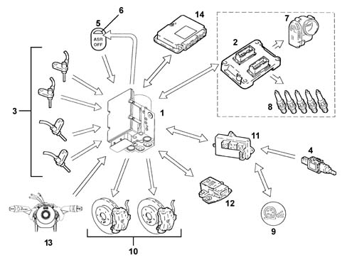
- 1 A.B.S./A.S.R. control unit
- 2 Engine management control unit
- 3 (Active) wheel rpm sensors
- 4 Brake pedal switch
- 5 A.S.R. on/off button
- 6 A.S.R. on/off LED
- 7 Motorized throttle body
- 8 Ignition system (advance variation)
- 9 ASR warning light in instrument panel
- 10 Brake pressure modulation
- 11 Body Computer
- 12 Slewing sensor
- 13 Steering angle sensor
- 14 Automatic transmission control unit
OPERATING LOGICS
Slipping of the drive wheels
Intervention - intervention times for good road grip conditions (asphalt)
Engine torque reduction by the engine management control unit through the alteration of the ignition advances, 6/100 of a second after the slipping limit is exceeded.
A further reduction in torque through a decrease in the throttle opening (by the engine management control unit through the motorized throttle body after 15/100 of a second).
Intervention of the hydraulic system (braking force on the drive wheels) after 2/10 of a second.
Operation in poor grip conditions
The system is capable of recognizing these conditions by comparing the acceleration of the drive wheels with the torque transmitted by the engine (engine load from the engine management control unit).
The system behaves in the same way as for both drive wheels slipping in good road grip conditions (asphalt) and the intervention levels are at the lower limit.
Slipping of one drive wheel only
intervention-intervention times
Torque reduction by the engine management control unit through the alteration of the ignition advances, 6/100 of a second after the slipping limit is exceeded.
A further reduction in torque through a decrease in the throttle opening (by the engine management control unit through the motorized throttle body after 15/100 of a second).
Intervention of the hydraulic system, a braking action exerted on the wheel that it slipping to guarantee a resistive force on the side with poor grip (T.C.).
This resistant force allows the differential to transmit the residual torque with grip at the wheel that is not slipping.
Slipping of one wheel round bends in good grip conditions (asphalt)
The system recognizes the bend from the speed of the rear wheels (driven).
It implements the same operating mode described for the "Slipping of one drive wheel only" condition, the intervention levels are at the upper limit. The torque reduction is applied gently.
Slipping of one wheel round bends in poor grip conditions (snow, ice)
The system implements the same operating mode described for the "Slipping of one drive wheel only" condition with the intervention levels at the lower limit. The torque reduction is accentuated (to ensure good side road holding).
In the ASR intervention conditions with the control unit simultaneously receiving the signal coming from the brake lights switch, the system excludes intervention on the brakes. The section relating to the torque reduction remains activated.
During acceleration, with the brake lights switch activated and maximum braking pressure (e.g. switch defective, ect.), if the system detects a difference in speed between the two front and rear wheels which implies the intervention of the ASR, the torque reduction only is implemented, the intervention on the brakes is excluded.
Adjustment of engine braking torque during deceleration
Vehicle instability during deceleration in poor grip conditions
The system recognizes this condition from the engine load, from the speed of the front and rear wheels and from the brake pedal sensor. In this case there is an increase in drive torque through the intervention of the engine management control unit opeing the motorized throttel to overcome the natural instability of the vehicle due to the engine braking torque in poor grip conditions.
ASR/MSR system exclusion
If the system is excluded using the button in the centre console, which is advisable when the vehicle is travelling over difficult surfaces (e.g. snow, ice, deep mud, sand or gravel) or when snow chains are fitted on the drive wheels, the ABS and EBD functions remain activated.
Intervention levels
The different intervention levels between 2 and 6 km/h depend on environmental factors; some of the conditions have been described in the operating logics, others are:
- high acceleration level
- vehicle speed (see graph)
- type of tyres (normal or winter); with winter tyres and good grip, high intervention levels, e.g. with winter tyres and poor grip, low intervention levels. The system is capable of recognizing these conditions by comparing the acceleration of the drive wheels with the torque transmitted by the engine (engine load from the engine management control unit).
The ASR function is activated in all vehicle speed conditions, however, the intervention of the brakes is excluded above 80 km/h.
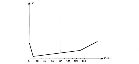
- K - Slipping level
ASR/MSR system failure
If there is a fault in the ABS, the ASR is also disabled. The following problems result in the ASR system only being excluded:
- C-CAN line errors
- interference with the speed signals
- interference with the drive wheel speed signals.
When these problems occur, the control unit activates the warning lights in the instrument panel and in the button.
The ASR warning lights logic is:
- with the ASR on, the warning light in the instrument panel is off and the LED in button is off
- with the ASR operating, the warning light in the instrument panel is intermittent and the LED in the button is off
- with the ASR switched off, the warning light in the instrument panel is on, the warning light in the button is on and there is an ASR not on message in the DOT matrix display
- with the ASR faulty, the warning lights in the instrument panel and the button are on and a fault message is shown on the DOT matrix display
The warning lights are operated by the ABS control unit via the C-CAN.
To ensure the drive of the vehicle (drive wheels) with snow chains fitted or in particular road surface conditions (snow, ice, deep mud, sand or gravel) it is advisable to switch the A.S.R. off.
Operation of the hydraulic system
The electro-hydraulic unit on the version equipped with ASR has 4 additional solenoid valves.
When the (normally closed) intake solenoid valve is activated, the additional quantity of fluid required to increase the pressure and brake the wheel(s) can be received.
When the (normally open) solenoid valve is activated it allows the modulated pressure produced by the pump necessary for the intervention of the ASR to be maintained in the brake caliper-pump circuit.
With the brake pedal pressed, the electronic control unit:
- does not supply the (N.C.) intake solenoid valve (2).
- does not supply the (N.A.) solenoid valve (3).
In this way the system operates during the following stages:
- pressure increase;
- pressure maintenance;
- pressure reduction
with the Lucas ESP ABS system
(See assembly ) 3340A ABS check/adjustment devices
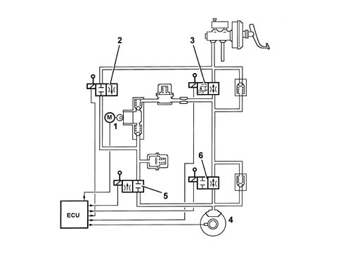
- 1 Pump
- 2 Intake solenoid valve
- 3 Operating solenoid valve
- 4 Brake caliper
- 5 Normally closed discharging solenoid valve
- 6 Normally open pressurizing solenoid valve
When the ASR/TC function is switched on, the electronic control unit:
- supplies the hydraulic pump (1)
- supplies the (N.C.) intake solenoid valve (2)
- supplies the (N.A.) solenoid valve (3).
Therefore the pressure produced by the pump (1) reaches the brake caliper and is modulated, on the request of the electronic control unit, by the discharge (5) and pressurizing (6) solenoid valves.
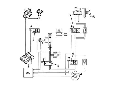
- 1 Pump
- 2 Intake solenoid valve
- 3 Operating solenoid valve
- 4 Brake caliper
- 5 Discharging solenoid valve
- 6 Pressurizing solenoid valve
DESCRIPTION OF COMPONENTS
Electro-hydraulic unit
The electro-hydraulic unit consists of a control unit and an electro-hydraulic control unit.
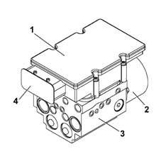
- 1 Electronic control unit
- 2 Recover pump motor
- 3 Electro-hydraulic unit casing
- 4 Electrical connection
Electronic control unit
The electronic control unit carries out the following functions:
- acquiring the data coming from the wheel rpm sensors
- memorizing the control parameters defined during the vehicle P.D.I.
- memorizing the software
- processing the data acquired
- controlling the braking process
- detecting faults in the braking system components
- memorizing the fault codes and activating the ABS/EBD/ASR warning lights
- transmitting and receiving data via the diagnostic connector
- conversing with the engine management control unit
- controlling the ASR/MSR process
- transmitting and receiving data via the C-CAN line.
Control unit connector
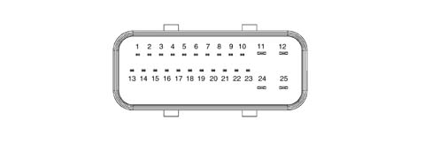
PIN OUT
| Pin | Function |
|---|---|
| 1 | CAN-L line |
| 2 | CAN-H line |
| 3 | ASR switch |
| 4 | ASR switch warning light |
| 5 | N.C. |
| 6 | Diagnostic line K |
| 7 | Right front sensor positive |
| 8 | Right front sensor signal |
| 9 | Right rear sensor positive |
| 10 | Right rear sensor signal |
| 11 | Earth |
| 12 | +30 supply |
| 13 | CAN-L line |
| 14 | CAN-H line |
| 15 | N.C. |
| 16 | VSO vehicle speed (recovery) |
| 17 | N.C. |
| 18 | N.C. |
| 19 | Left front sensor positive |
| 20 | Left front sensor signal |
| 21 | Left rear sensor positive |
| 22 | Left rear sensor signal |
| 23 | +15 supply |
| 24 | Pump earth |
| 25 | +30 pump supply |
Electro-hydraulic control unit
Specifications
It has the task of modulating the pressure of the fluid at the brake calipers via solenoid valves with the following operating stages:
- brake fluid pressure increase
- brake fluid pressure maintenance
- brake fluid pressure decrease.
Composition
The electro-hydraulic control unit consists of:
- twelve 2-way solenoid valves
- a dual circuit recovery pump
- two low pressure accumulators
- two high pressure accumulators.
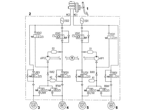
- 1 Brake servo brake pump assembly
- 2 Electro-hydraulic control unit
- 3 Left rear wheel
- 4 Right front wheel
- 5 Left front wheel
- 6 Right rear wheel
Active sensors
Specifications
For the active sensors, see the ABS
(See subassembly ) 3340 ANTI-LOCK BRAKING SYSTEM (A.B.S.)
ASR on/off button
Function
It has the task of switching the ASR/MSR system off and has an LED.
The button is in the centre console
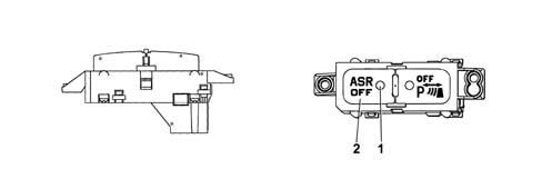
- 1 LED
- 2 Off button
General remarks
The ESP continuously recognizes a loss in grip for the wheels, both longitudinal and transverse, in all driving conditions from braking to acceleration in order to ensure the direction and the stability of the vehicle.
The management of the ESP system is entrusted to the A.B.S. electronic control unit, integrated with a special electro-hydraulic control unit, that allows action on the braking system independently of the action of the user.
The control unit processes the following signals:
- steering wheel rotation angle
- lateral acceleration and slewing
- motorized throttle position
- wheel rpm
- hydraulic braking system pressure
and uses special algorithms in the electronic control unit software to obtain the figures for the dynamic control of the vehicle:
- longitudinal and transverse sliding between the wheels and the road surface
- axle drift.
Using these figures the system interprets the effective dynamics of the vehicle; having identified all the critical conditions due to environmental factors (e.g. surface with poor grip) or any errors made by the user (e.g. panic situations) and with subsequent intervention on the brakes and the drive torque, the vehicle is restored to good driving conditions.
The system interfaces with:
- N.C.M. for drive torque adjustment,
- N.B.C. (Body Computer Node) for the transmission of the vehicle speed and the control of the warning lights.
The exchange of information between these components takes place via the C-CAN and B-CAN lines.
There is a dedicated line (line K) for the diagnosis of the system.
The system is combined with a power unit with a specific brake pump; in addition, the pipes between the brake pump and the A.B.S. control unit have a Titaflex insert because the diameter of the pipe (6mm) is larger than regular pipes (4 mm); this is designed to prevent adverse effects on the operation of the ESP at low brake fluid temperatures.
The ESP system switches on automatically when the vehicle is started up and cannot be switched off by the user; the button in the centre console only switches off the A.S.R. function and only when advisable (see A.S.R. system).
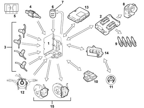
- INPUT SIGNALS:
- - Wheel speed sensors (from direct line) (3)
- - Brake pedal switch (from C-CAN line) (4)
- - ASR off button (from direct line) (6)
- - Engine management control unit (2)
- - Throttle angle position (from C-CAN line)
- - Body computer (14)
- - Handbrake signal (from C-CAN line)
- - Warning light status signal (from C-CAN line) (11)
- - Slewing sensor (rotation of vehicle on vertical axis) (from C-CAN line) (10)
- - Lateral acceleration sensor (from C-CAN line) (10)
- - Steering angle/steering wheel rotation sensor (from C-CAN line) (12)
- - Automatic transmission control unit (gear engaged status) (from C-CAN line) (13)
- - Hydraulic system pressure sensor (from direct line) (1)
- OUTPUT SIGNALS:
- - Brake pressure modulation control (15)
- - Ignition advance reduction control (from C-CAN line) (9)
- - Engine power management control (from C-CAN line) (8)
- - Gear change inhibition (from C-CAN line) (13)
- - Wheel speed signal for speedometer and milometer (from C-CAN) (14)
- - VSO signal (vehicle speed) (14)
- - ESP warning light in instrument panel control (from C-CAN line) (11)
- - ASR off LED (7)
OPERATING LOGICS
As stated previously, in addition to controlling the slipping of the vehicle in a lengthwise direction, the ESP system also controls slipping in a sideways direction and, as a result, controls the lateral stability of the vehicle.
The lateral stability of a vehicle depends on the reaction of the tyres to lateral forces and the adhesion force of the wheel with the road surface.
It should be remembered that the adhesion force of a wheel depends on the vertical load which depends on the situation the wheel finds itself in (resting or no load) and on the friction coefficient which depends on the road surface and tyre conditions.
When the vehicle is travelling in a straight line, the lateral forces do not really have an effect unless outside factors that increase its intensity intervene (e.g. a gust of wind or a change to a different surface), unlike when driving round a bend where there is a strong increase in lateral forces due to the centrifugal force.
The action of the lateral forces produce a variation in the drift angle of the wheels and, consequently, a variation in the axle drift (drift angle = difference between the desired route and the effective route).
The lateral forces do not, however, act equally on all four wheels because they are not subject to the same load conditions, in effect the load on the wheel differs depending on the situation the wheel is in, namely:
- acceleration (lightening of the front axle and loading of the rear axle)
- braking (loading of the front axle and lightening of the rear axle)
- bend to the right/left (loading or the outer wheels and lightening of the inner wheels)
- accelerating/decelerating round a bend (combination of the cases mentioned above).
It is obvious that if the lateral forces acting on the individual wheels vary, there will also be a variation in the forces acting on the vehicle axles; consequently the lateral forces acting on the front axle overcome those on the rear axle and viceversa determining a rotation (moment0 on the vehicle axis of the vehicle (slewing axis).
The moment of slewing affects the behaviour of the vehicle producing either understeer or oversteer.
Understeer for a vehicle is defined as the drift angle of the front axle increasing, during increasing lateral acceleration, greatly compared with that of the rear axle. In this case, when the vehicle is driving round a bend, it will tend to go straight (take the bend wide).
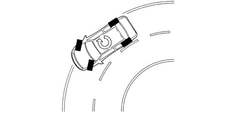
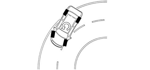
Oversteer for a vehicle is when, with increasing transverse acceleration, the drift angle for the rear axle increases greatly compared with that of the front axle. In this case the vehicle tends to "do an about-face" (the rear axle tends to move to the outside of the bend, therefore the vehicle "hugs" the bend).
In order to keep the effect of lateral forces under control and limit the slewing moment, the A.B.S. control unit must firstly calculate the behaviour of vehicle set by the driver using:
- steering wheel angle sensor
- accelerator pedal position
- brake circuit pressure
after which the control unit should check the actual behaviour of the vehicle through:
- the wheel sensors (vehicle speed/wheel speed),
- lateral acceleration sensor
- slewing sensor
As can be deduced from what has been said earlier, the control unit is capable of:
- detecting actions carried out by the user, in effect, through the position of the steering wheel it checks the number of degrees (wide radius or narrow radius bends) and the speed for rotating the steering wheel (sharp or gentle rotations) and, using the position of the throttle and the brake pressure when accelerating or braking, how the user is taking the bend or deviating from the straight path.
- detecting the actual behaviour of the vehicle given the environmental variables, e.g. slippery surface, reaction of the vehicle to incorrect manoeuvres by the user, etc., in order to identify the moment of slewing and the lateral sliding of the axles via the sensors on the four wheels and the slewing/lateral acceleration sensor.
These two operations are necessary to superimpose the mathematical model mapped in the control unit on the effective behaviour of the vehicle in order to identify the state in which the vehicle is in (understeer or oversteer) and decide the action for the brakes and the engine
Understeer round bends
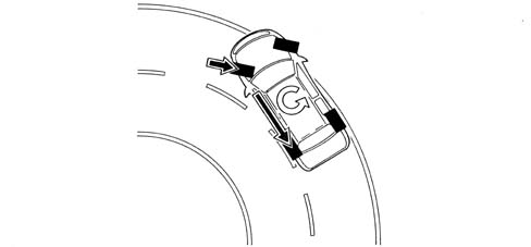
The control unit verifies the presence of understeer (mainly from the drift of the front axle), corrects the behaviour of the vehicle, braking the inner wheels round the bend in order to create an opposing moment which will lead the vehicle towards the centre of the bend and, possibly, reducing the drive torque.
Oversteer round bends
In the presence of understeer (mainly from the drift of the rear axle) the control unit corrects the behaviour of the vehicle, braking the outer front wheel round the bend in order to create an opposite slewing moment, if necessary increasing the drive torque.
The system intervenes before the oversteer and understeer values are too high in order to limit the corrective measures that have to be taken which could make handling difficult.
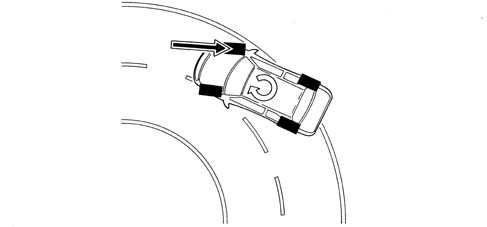
Sharp variations from the straight path (slalom/overtaking)
In the case of sharp variations from the path (e.g. overtaking, slalom), the control unit identifies possible oversteer and understeer conditions and corrects the path of the vehicle acting as described in the cases mentioned previously.
Sharp variation from the straight path (driving on different surfaces)
The control unit is capable of detecting deviations in the path and the prevalence of axle drift, correcting the path through suitable action on the brakes and the engine.
Sharp acceleration/deceleration
The control unit uses the A.S.R./M.S.R. strategy also controlling the lateral acceleration of the vehicle and, as a result, regulating the action on the front and rear brakes and on the engine torque in a more complete way than on vehicles with ASR only.
A.S.R. exclusion
If the A.S.R./M.S.R. is excluded, the following functions remain activated:
- A.B.S./E.B.D.
- T.C. up to a speed of 40 km per hour
- ESP
ESP intervention display
The intervention of the ESP system is shown by the special warning light in the instrument panel flashing (5 Hz d.c. 50%).
the ESP system improves driving safety but there are limited situations which cannot be controlled by the ESP system, therefore it is not seen as a device which improves the performance of the vehicle but as a device that improves the safety of the vehicle.
Diagnostic functions
The ABS control unit is capable of carrying out the autodiagnosis of the system and, in the case of a fault, can:
- deactivate the entire system
- partly deactivate the syste (maintaining the ABS/EBD function).
Below is a list of the faults that can be detected by the control unit, the status of the warning lights and the type of recovery used.
| Error | ABS warning light | EBD warning light | ESP warning light | Recovery |
|---|---|---|---|---|
| Right front sensor electrical error | ON | OFF | ON | R3 |
| Left front sensor electrical error | ON | OFF | ON | R3 |
| Right rear sensor electrical error | ON | OFF | ON | R3 |
| Left rear sensor electrical error | ON | OFF | ON | R3 |
| Right front sensor error | ON | OFF | ON | R3 |
| Left front sensor error | ON | OFF | ON | R3 |
| Right rear sensor error | ON | OFF | ON | R3 |
| Left rear sensor error | ON | OFF | ON | R3 |
| Right front ABS discharge valve | ON | ON | ON | R2 |
| Right front ABS pressurizing valve | ON | ON | ON | R2 |
| Left front ABS discharge valve | ON | ON | ON | R2 |
| Left front ABS pressurizing valve | ON | ON | ON | R2 |
| Left rear ABS discharge valve | ON | ON | ON | R2 |
| Left rear ABS pressurizing valve | ON | ON | ON | R2 |
| Right rear ABS discharge valve | ON | ON | ON | R2 |
| Right rear ABS pressurizing valve | ON | ON | ON | R2 |
| Main valve 1 (VLV1) | ON | ON | ON | R2 |
| Main valve 2 (VLV2) | ON | ON | ON | R2 |
| Operating valve 1 (USV1) | ON | ON | ON | R2 |
| Operating valve 2 (USV2) | ON | ON | ON | R2 |
| Pump motor | ON | OFF | ON | R3 |
| Valve relay | ON | ON | ON | R2/R5 |
| NA NC brake light switch | ON | OFF | ON | R3 |
| Lateral acceleration sensor (AY) | OFF | OFF | ON | R4 |
| Slewing sensor | OFF | OFF | ON | R4 |
| Brake fluid pressure sensor | ON | OFF | ON | R3 |
| Lambda 6 (magnetic wheel malfunction) | ON | ON | ON | R1 |
| NOTB (implementation irregularity) | ON | OFF | ON | R5/R3 |
| Steering angle sensor | OFF | OFF | ON | R4 |
| CAN-BUS | OFF | OFF | ON | R4 |
| Engine CAN message errors | OFF | OFF | ON | R4 |
| Control unit | ON | ON | ON | R1 |
| Supply voltage | ON | ON | ON | R2 |
| Variant Coding (vehicle configuration received from CAN incorrect) | ON | ON | ON | R1 |
| Communication with failure warning lights | ON | ON | ON | ON |
OPERATION OF WARNING LIGHTS
The ABS control unit activates the warning lights according to the following logic:
- with the ESP on, the warning light in the panel is off and the warning light in the ASR ESP button is off
- with the ASR switched off, the ESP warning light in the panel is off but there is a message in the DOT matrix display saying the ASR is off and the warning light in the button is on
- with the ESP activated, the warning light in the panel flashes and the warning light in the button is off
- with the ESP faulty, the warning light in the panel is on and there is a message in the dot matrix display.
As the system is connected to the C-CAN line it has a diagnostic line known as line K. The diagnosis of the system can be carried out using the diagnostic equipment connected to the diagnostic socket in the N.B.C. (Body Computer Node).
DESCRIPTION OF COMPONENTS
Operation of the hydraulic system
The electro-hydraulic unit on the version equipped with ESP has 4 additional solenoid valves.
When the (normally closed) intake solenoid valve is activated, the additional quantity of fluid required to increase the pressure and brake the wheel(s) can be received.
When the (normally open) solenoid valve is activated, the modulated pressure produced by the supply pump can be maintained in the circuit.
When the ESP system is not intervening, the electronic control unit:
- does not activate the (N.C.) intake solenoid valve (2).
- does not activate the (N.A.) operating solenoid valve (3).
In this way the system operates during the following stages:
- pressure increase;
- pressure maintenance;
- pressure reduction
- pressure increase and resupply
with the Lucas ESP ABS system
(See assembly ) 3340A ABS check/adjustment devices
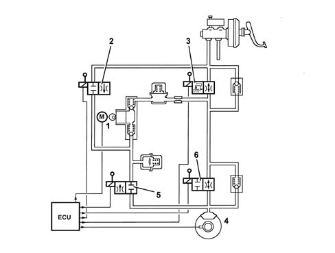
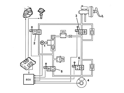
During the intervention of the ESP system, the electronic control unit:
- activates the hydraulic pump (1)
- activates the (N.C.) intake solenoid valve (2).
- activates the (N.A.) operating solenoid valve (3).
Therefore the pressure produced by the pump (1) reaches the brake caliper and is modulated, on the request of the electronic control unit, by the discharge (5) and pressurizing (6) solenoid valves.
DESCRIPTION OF COMPONENTS
Electro-hydraulic unit
The electro-hydraulic unit consists of an electronic control unit and an electro-hydraulic control unit.
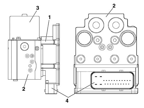
- 1 Electronic control unit
- 2 Electro-hydraulic control unit
- 3 Recovery pump
- 4 25 pin connector
Electronic control unit
The electronic control unit carries out the following functions:
- processing the data acquired
- controlling the braking process
- detecting faults in the braking system components
- memorizing the fault codes and activating the ABS/EBD/ASR/VDC warning lights
- transmitting and receiving data via the diagnostic connector
- conversing with the engine management control unit
- controlling the ASR/MSR/ESP process
- transmitting and receiving data via the C-CAN line
- conversing with the robotized transmission (NCR).
- acquiring the data coming from the wheel rpm sensors
- memorizing the control parameters defined during the vehicle P.D.I.
- memorizing the software
Pin out
The control unit is conected to the electrical system via a 25 pin connector.
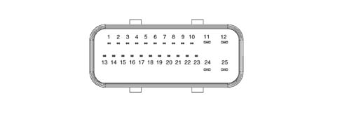
| Pin | Function |
|---|---|
| 1 | CAN-L line |
| 2 | CAN-H line |
| 3 | ASR switch |
| 4 | ASR switch warning light |
| 5 | N.C. |
| 6 | Diagnostic line K |
| 7 | Right front sensor positive |
| 8 | Right front sensor signal |
| 9 | Right rear sensor positive |
| 10 | Right rear sensor signal |
| 11 | Earth |
| 12 | +30 supply |
| 13 | CAN-L line |
| 14 | CAN-H line |
| 15 | N.C. |
| 16 | VSO vehicle speed |
| 17 | N.C. |
| 18 | N.C. |
| 19 | Left front sensor positive |
| 20 | Left front sensor signal |
| 21 | Left rear sensor positive |
| 22 | Left rear sensor signal |
| 23 | +15 supply |
| 24 | Pump earth |
| 25 | +30 pump supply |
Electro-hydraulic control unit
It has the task of modulating the pressure of the fluid at the brake calipers via solenoid valves with the following operating stages:
- brake fluid pressure increase
- brake fluid pressure maintenance
- brake fluid pressure decrease.
The electro-hydraulic control unit is available as spares filled with fluid; take care not to remove the protective caps or turn it upsidedown whilst moving it.
A sensor is fitted on the electro-hydraulic control unit for monitoring the pressure of the brake; this sensor is supplied together with the hydraulic unit so it cannot be replaced individually.
Composition
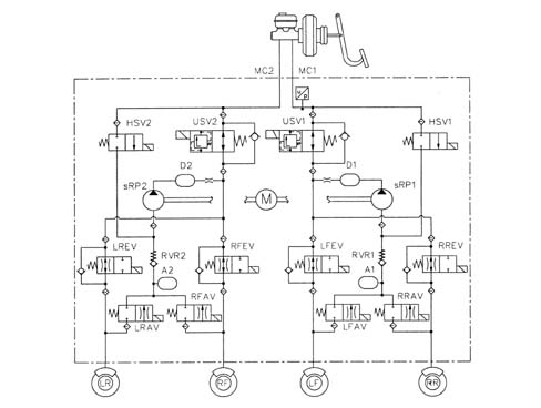
The electro-hydraulic control unit consists of:
- twelve 2-way solenoid valves
- a dual circuit recovery pump
- two low pressure accumulators
- two high pressure accumulators
- brake fluid pressure sensor.
Steering sensor
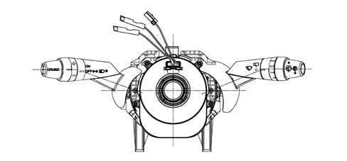
The steering angle sensor has the task of measuring the angles in degrees and the rotation speed of the steering wheel and making these figures available via the C-CAN (steering angle sensor node).
Composition
The sensor is incorporated in the steering column switch unit.
Operation
The sensor measures the following via internal electronics:
- the angular position of the steering column
- the rotation speed of the steering column.
This information is processed directly by the sensor and is made available at the brake node via the C-CAN.
The sensor must be zeroed in relation to the position of the steering wheel in order to work properly. This is done using the diagnostic equipment (see instructions with the EXAMINER).
The sensor has an autodiagnostic function and is capable of carrying out a check on the plausibility of the information processed.
Lateral acceleration/slewing sensor
The two slewing and lateral acceleration sensors are designed to measure rotation of the vehicle on the vertical axis (slewing) and lateral acceleration.
The connection to the ABS control unit is direct.
Composition
The sensor consists of a plastic casing that houses the sensitive elements which detect slewing and lateral acceleration and the electronic management.
The sensor has a connector with six pins all of which are connected.
| Pin | Function |
|---|---|
| 1 | +15 supply |
| 2 | C-CAN line |
| 3 | L-CAN line |
| 4 | H-CAN line |
| 5 | E-CAN line |
| 6 | Earth |
Location
The sensor is located at the centre of gravity, on the tunnel between the two front seats.
Operation
The sensor receives a direct positive supply controlled by the ignition.
The acceleration and slewing information is made available at the brake node via the C-CAN
Active sensors
For the active sensors, see the ABS
(See subassembly ) 3340 ANTI-LOCK BRAKING SYSTEM (A.B.S.)
ASR on button
For the ASR off button, see
Parts & tools for this job Staging For 2002 Lancia Thesis
- PARTBrake padsSearch: Lancia Thesis 2002 brake pads
- TOOLBrake bleeder kitSearch: one man brake bleeder kit
- FLUIDBrake fluidSearch: brake fluid
Links open Amazon search results in a new tab. As an Amazon Associate I earn from qualifying purchases.