
Traction control: Specifications
- Make
- Lancia
- Model
- Thesis Factory Service Manual
- Year
- 2002–2009
- Section
- Traction control › Specifications
Specifications
In addition to the ABS EBD system, the vehicle is also equipped with a system for controlling the stability of the vehicle (ESP) which includes the drive control system (ASR/MSR).
The ESP system, in particular, thanks to slewing sensors and steering wheel angle sensors, guarantees the monitoring of the dynamics of the entire vehicle thereby improving active safety.
Function
This system, in addition to the normal anti-lock and brake distribution functions controlled by the ABS with EBD, also carries out the following functions:
- acceleration slipping adjustment (A.S.R.)
- adjustment of the engine braking torque (M.S.R.)
- locking the differential through action on the brakes (T.C.).
These functions are carried out through action on the drive torque and the application of a braking force on one or both the drive wheels.
If, during acceleration, one or both the drive wheels tend to slip, the ABS control unit asks the engine management control unit to reduce the torque transmitted to the wheels and, almost at the same time, without any intervention by the user, brakes the wheel or wheels.
If, in the case of strong deceleration, the wheels tend to lock, the ABS control unit requests the engine management control unit to adjust the engine braking torque in order to prevent the instability of the vehicle.
The system can be excluded by activating the button in the centre console.
The LED in the button comes on and the message is shown in the DOT matrix display in the instrument panel signalling that the ASR/MSR system has been switched off.
The warning light in the button coming on and the repetition on the DOT matrix indicates that the system has been switched off due to a fault recorded by the control unit
The intervention of the ASR/MSR is signalled by the flashing of the warning light in the instrument panel.
Each time the vehicle is started up the ASR/MSR function is activated even if the function was switched off when the vehicle was switched off.
COMPOSITION
Structure
The system consists of:
- a specific electronic control unit integrated with the electro-hydraulic control unit
- an electro-hydraulic control unit that modulates the pressure acting on the brakes, independently of the action by the user, by means of twelve solenoid valves
- four ACTIVE type sensors
- specific wiring.
Driving a vehicle in all conditions where the physical limits of grip and, consequently, stability may be reached can be a difficult task for the average driver therefore in order to further improve safe driving conditions an electronic system capable of assisting the driver with this difficult task is available.
The systems currently employed to ensure safer driving in particular conditions are mainly the A.B.S. which controls braking and the T.C. and A.S.R./M.S.R. systems which control traction during acceleration through action on the brakes (T.C.) and traction/drive torque during acceleration and release through action on the brakes and on the engine control system motorized throttle (A.S.R./M.S.R.).
The ESP system (Electronic Stability Program) includes all the above listed functions ensuring optimum dynamic control of the vehicle with the addition of specific sensors:
- steering angle sensor on the steering wheel
- slewing/lateral acceleration sensor at the centre of gravity under the centre tunnel.
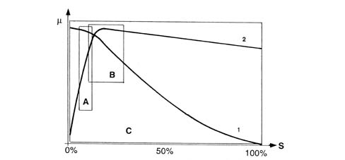
- m - Wheel grip
- S - Slipping
- A - EBD intervention area
- A - ABS intervention area
- C - ESP intervention area
- 1 Lateral force curve
- 2 Longitudinal force curve
As can be seen from the grip/slipping diagram, the area covered by the ESP system is larger than that covered by a conventional ABS/EBD system.
The ESP system cannot be switched off as it is a safety system; the A.S.R./M.S.R. function, on the other hand, can be switched off via the button in the centre console.
The intervention of the ESP system is signalled by a special warning light in the instrument panel node (N.Q.S.)
Parts & tools for this job Staging For 2002 Lancia Thesis
- PARTBrake padsSearch: Lancia Thesis 2002 brake pads
- TOOLBrake bleeder kitSearch: one man brake bleeder kit
- FLUIDBrake fluidSearch: brake fluid
Links open Amazon search results in a new tab. As an Amazon Associate I earn from qualifying purchases.