
Manual gearbox ml5c
- Make
- Fiat
- Model
- Ulysse Factory Service Manual
- Year
- 2002–2010
- Section
- Manual gearbox with differential › Manual gearbox ml5c
MANUAL GEARBOX ML5C
INTRODUCTION
The gearbox is transverse type with 5 forward speeds plus reverse.
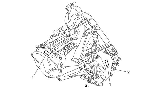
- 1 Identification plate
- 2 oil filler plug
- 3 oil drain plug
The following diagram shows a cross section through the gearbox.
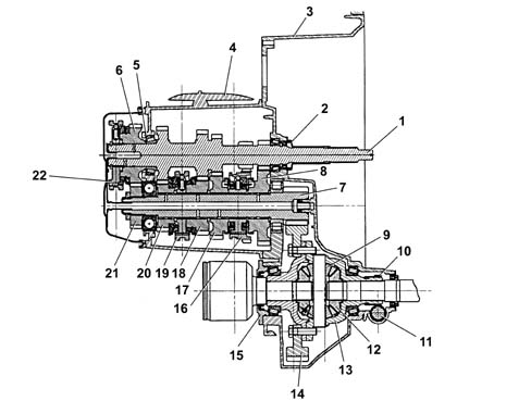
- 1 Main shaft
- 2 guide pipe
- 4 gearbox casing
- 5 main shaft clearance adjustment
- 6 5th speed drive gear
- 7 layshaft
- 9 planet gears
- 10 worm screw (speedometer)
- 11 gearbox speed outlet gear
- 12 differential gears
- 13 differential housing
- 14 ring gear
- 15 differential fastening plate
- 16 1st and 2nd speed synchroniser
- 17 2nd speed driven gear
- 18 3rd speed driven gear
- 19 3rd and 4th speed synchroniser
- 20 4th speed driven gear
- 21 2nd speed driven gear
- 22 5th speed synchroniser
- 3 clutch casing
- 8 1st speed driven gear
The ML5C gearbox can be broken down into 4 different assemblies
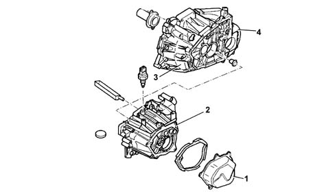
- 1 panel cover
- 2 gearbox gear casing
- 3 clutch casing
- 4 differential housing
DESCRIPTION OF COMPONENTS
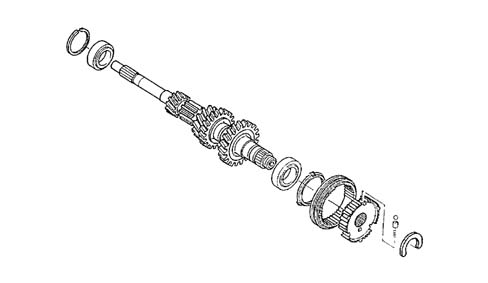
Main shaft
The main shaft consists of:
- 1 < SUP > st < /SUP >, 2 < SUP > nd < /SUP >, 3 < SUP > rd < /SUP >, 4 < SUP > th < /SUP > speed gears and reverse made out of one part,
- 5 < SUP > th < /SUP > speed gear fitted with its associated synchroniser.
The main shaft is supported by two taper roller bearings.
The coaxial clutch control device is fitted to the end of the main shaft.
Lay shaft
The lay shaft consists of:
- 1 < SUP > st < /SUP >, 2 < SUP > nd < /SUP >, 3 < SUP > rd < /SUP >, 4 < SUP > th < /SUP > and 5 < SUP > th < /SUP > speed gears are fitted on the shaft,
The layshaft is mounted on:
- a roller bearing on the pinion side
- a ball bearing on the cover side.
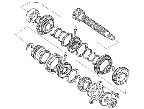
Synchronizers
The synchronisers are Borg Warner type with built-in balls.
1st and 2nd speed synchroniser
The 1st and 2nd sychroniser is double-cone type. Double-cone technology allows fast, effective synchronisation. The integrated system allows effective synchroniser neutrality with the synchroniser at rest (neutral position).
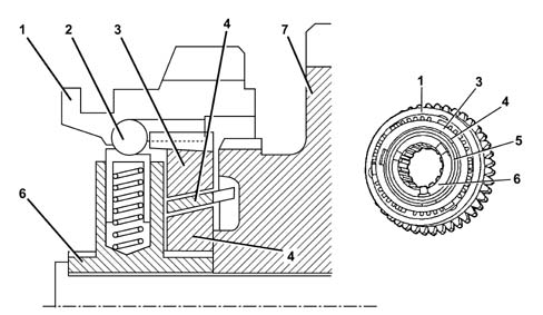
- 1 Control sleeve
- 2 ball
- 3 external synchroniser crown
- 4 twin cone
- 5 internal synchroniser crown
- 6 synchronizer hub
- 7 driven pinion
3rd and 4th speed synchroniser
The 3rd and 4th speed synchroniser is single cone type.
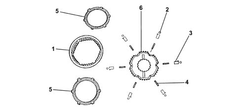
- 1 Control sleeve
- 2 ball
- 3 piston
- 4 piston spring
- 5 synchroniser crown
- 6 synchronizer hub
5th speed synchroniser
The 5th speed synchroniser is single cone type. It is located on the mainshaft to reduce gearbox noise.
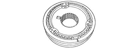
Precautions to be followed when refitting the synchronisers.
When refitting the 1rd and 2th speed synchroniser, ensure the components are fitted axially in relation to the shaft and the synchoniser components are positioned at an angle:
- Fit from the hub toward the sleeve,
- fit the pistons in their housings so that the notch on the piston is opposite the outer synchroniser crownwheel,
- fit the outer sleeve so that the chamfer on the sleeve is aligned with the notch on the piston.
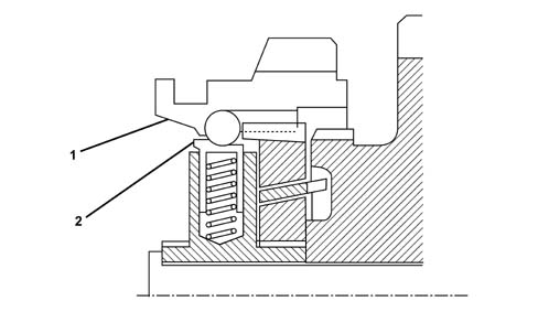
- 1 chamfer on sleeve
- 2 notch on piston
When refitting the 3rd and 4th speed synchroniser, ensure the components are fitted axially in relation to the shaft and the synchoniser components are positioned at an angle:
- Fit from the hub toward the sleeve,
- fit the outer sleeve so that the chamfer on the sleeve is aligned with the notch on the piston.
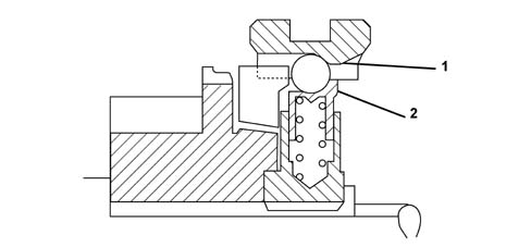
- 1 chamfer on sleeve
- 2 notch on piston
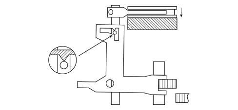
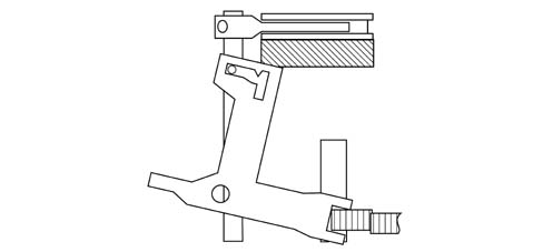
Reverse brake
This device allows main shaft rotation speed to be reduced quickly to ensure correct reverse engagement.
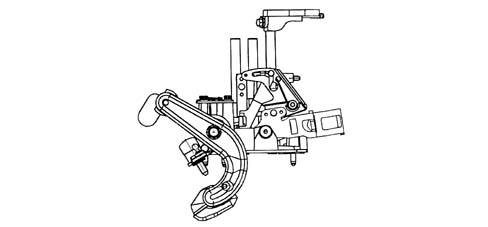
Operating principle
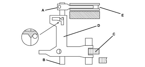
- A - 5th speed engagement fork
- B - 5th speed engagement control shaft
- C - reverse engagement pinion
- D - reverse engagement fork
- E - 5th speed synchroniser
Differential
The following figure shows the differential assembly
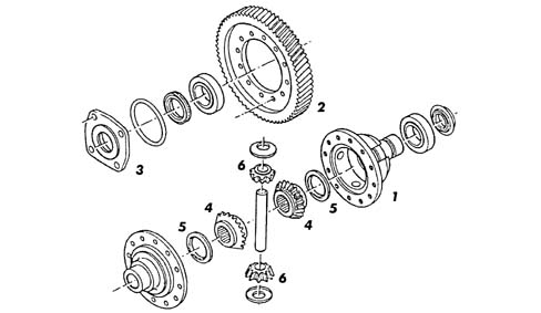
- 1 differential housing
- 2 ring gear
- 3 retaining bolt plate
- 4 differential gears
- 5 shims
- 6 planet gears
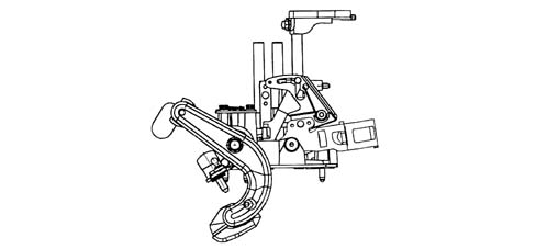
Gear selection control
The gear selection mechanism consists of a preassembled modular unit.
To improve gear engagement, the 1st and 2nd gear engagement shaft is fitted on ball bearings.
Gear selection is controlled by cables. The selection lever is fitted with a damping mass that reduces vibrations transmitted from the gearbox to the cables.
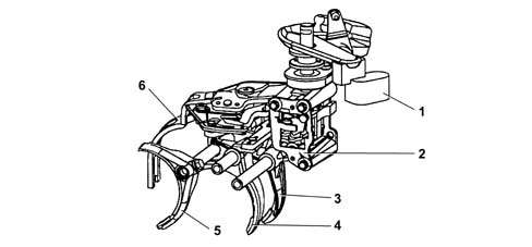
- 1 damping mass
- 2 reverse engagement lock plate
- 3 1st and 2nd speed engagement fork
- 4 3rd and 4th speed engagement fork
- A - 5th speed engagement fork
- 6 reverse engagement fork
The gear selection linkage includes a mechanism that prevents shifting directly from 5th speed to reverse.
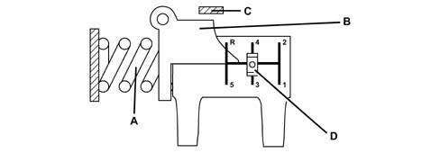
- A - spring
- B - reverse engagement lock plate
- C - selection/gear plate
- D - fixed detent
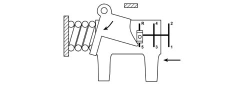
During selection for engagement of 5th speed, the selection plate moves left and turns the locking plate about its centre line.
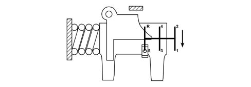
When the 5th speed is engaged, the selection plate turns about itself to release the locking plate, which returns to its original position.
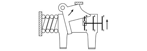
If an attempt is made to engage reverse directly, from a state of 5th speed engaged, the selection plate moves toward the locking plate which in turn locks against the fixed detent.
Parts & tools for this job Staging For 2002 Fiat Ulysse
- PARTClutch kitSearch: Fiat Ulysse 2002 clutch kit
- TOOLClutch alignment toolSearch: clutch alignment tool
- FLUIDGear oilSearch: Fiat Ulysse manual gearbox oil
Links open Amazon search results in a new tab. As an Amazon Associate I earn from qualifying purchases.