
Air bag module passanger side r r
- Make
- Fiat
- Model
- Ulysse Factory Service Manual
- Year
- 2002–2010
- Section
- Special accessories › Air bag module passanger side r r
AIR BAG MODULE PASSANGER SIDE R R
Refitting
Before removing and refitting the Air Bag module the following preliminary operations must be carried out: (1) turn the ignition key to the OFF position and extract it; (2) wait for 2 minutes before continuing; (3) remove the battery housing cover, disconnect the negative battery terminal and insulate the leads; (4) wait for 5 minutes before continuing.
FOLLOW ALL THE RECOMMENDED SAFETY INSTRUCTIONS (see assembly 5580C - AIR BAG SYSTEM).
- Rotate the engine through 90° on the overhaul stand.
- Remove the timing side engine support.
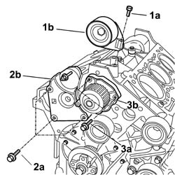
1. Undo the fixing bolts (1a) and remove the fixed timing belt tensioner (1b).
2. Undo the bolts (2a) and remove the moving timing belt tensioner support.
3. Undo the bolts (3a) and remove the crankshaft pulley (3b).
- Separate the water pump gasket.
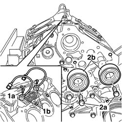
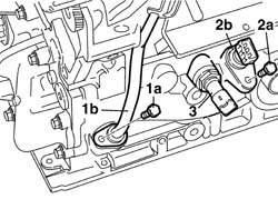
1. Undo the fixing bolts (1a) and remove the detonation sensors (1b).
2. Undo the bolts (2a) and remove the fixed timing belt tensioners (2b).
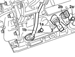
1. Undo the fixing bolt (1a) and remove the engine oil dipstick (1b).
2. Undo the fixing bolt (2a) and remove the engine oil temperature sensor (2b).
3. Undo and remove the engine oil pressure sensor.
Removing
Op. 7040H29 FRONT PILLAR LOWER COVER (ONE), LEFT OR RIGHT - R.R.
- < R1 > [Right side]
Op. 7040A45 FACIA RH SIDE COVER - R R
Op. 7040G22 FACIA COMPARTMENT LIGHT SWITCH/BULB HOLDER - R+R
Op. 7040A31 FLAP ASSEMBLY - R R
Op. 7040A74 TRIM UNDER CONTROL PANEL - R.R.
Op. 7040A68 GRILLE FOR CENTRE DASHBOARD SPEAKER - R.R.
- < R1 > [Both]
Op. 7040A63 CONNECT AND CLIMATE CONTROL SYSTEM CONTROL UNIT HOLDER TRIM IN CENTRE CONSOLE - R.R.
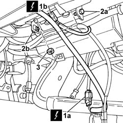
1. Disconnect the electrical connections (1a) and (1b).
2. Loosen the bolts (2a) and (2b) fixing the mounting bracket to the dashboard crossmember.
3. Undo the nuts fixing the Air Bag module and mounting bracket to the dashboard crossmember.
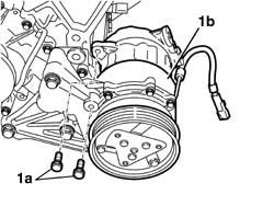
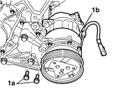
1. Undo the retaining bolts (1a) and remove the air conditioning compressor (1b).
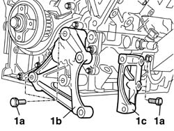
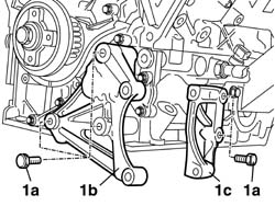
1. Undo the bolts (1a) and remove the air conditioning compressor support (1b) and support (1c).
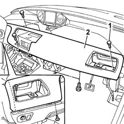
1. Undo the bolts fixing the dashboard front trim.
2. Remove the front dashboard trim complete with Air Bag module.
- Place the Air Bag module in the special cupboard, resting it on a free surface with the bag facing upwards.
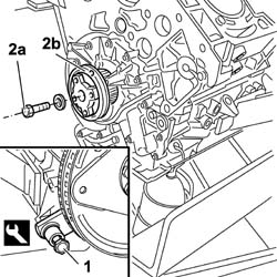
1. Fit the flywheel lock.
2. Undo the bolt (2a) and remove the timing belt toothed drive pulley (2b).
| Description | Code | Function | |
|---|---|---|---|
| 1 | Counter-torque | 1.860.846.000 |
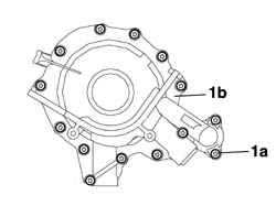
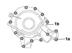
1. Undo the fixing bolts (1a) and remove the crankshaft front oil seal cover with built-in oil pump (1b).
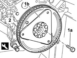
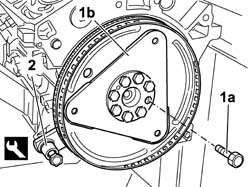
1. Undo the bolts (1a) and remove the engine flywheel (1b).
2. Remove the flywheel lock.
| Description | Code | Function | |
|---|---|---|---|
| 2 | Counter-torque | 1.860.846.000 |
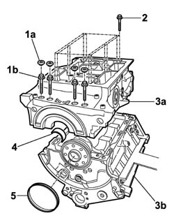
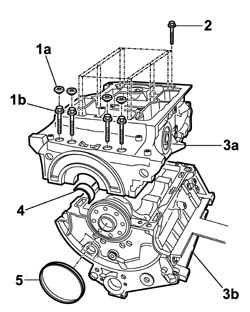
1. Undo and remove the plugs (1a), then undo the bolts underneath (1b) fixing the the lower crankcase with a main bearing cap function.
2. Undo the remaining bolts fixing the lower crankcase to the upper crankcase.
Before dismantling the crankshaft, mark the position of the crankshaft bearings and the thrust washers to avoid refitting them incorrectly.
3. Separate the lower crankcase (3a) from the upper crankcase (3b) and place it on a special workbench.
4. Remove the lower main journal half-bearings.
5. Remove the crankshaft rear oil seal
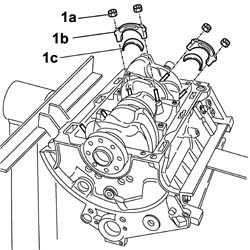
Before dismanling the connecting rod-piston assemblies, mark the crankpins and the half-bearings to avoid refitting them incorrectly.
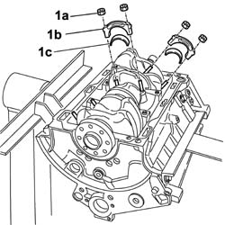
1. Undo the nuts (1a) and remove the connecting rod caps (1b) complete with half bearings (1c).
Refitting
- Observe the following precaution.
Handle the Air Bag module very carefully. Make sure that the battery is disconnected.
- If a new module is being fitted, position the labels. Remove the detachable part of the adhesive label from the new module and place it in the special folder containing the vehicle details (model, registration date, chassis number) and the serial number of the old module. The file should be kept for future checks. A new adhesive plate comes together with the module and should be stuck on top of the existing one. Beforehand, however, it should be perforated at the month and 10 years after the year in which the module is being fitted (e.g. 2010 for 2000).
- Position the front dashboard trim complete with Air Bag module.
- Tighten the nuts fixing the Air Bag module and mounting bracket to the dashboard crossmember.
| Value - daNm | Fastening | Component | Ø | |
|---|---|---|---|---|
| 4 (PASSENGER SIDE) | nut | MECH. MODULE AIR BAG ASSEMBLY |
- Tighten the bolts fixing the mounting bracket to the dashboard crossmember.
- Tighten the bolts fixing the dashboard front trim.
- Connect the electrical connections.
Op. 7040A63 CONNECT AND CLIMATE CONTROL SYSTEM CONTROL UNIT HOLDER TRIM IN CENTRE CONSOLE - R.R.
Op. 7040A68 GRILLE FOR CENTRE DASHBOARD SPEAKER - R.R.
- < R1 > [Both]
Op. 7040A74 TRIM UNDER CONTROL PANEL - R.R.
Op. 7040A31 FLAP ASSEMBLY - R R
Op. 7040A45 FACIA RH SIDE COVER - R R
Op. 7040G22 FACIA COMPARTMENT LIGHT SWITCH/BULB HOLDER - R+R
Op. 7040H29 FRONT PILLAR LOWER COVER (ONE), LEFT OR RIGHT - R.R.
- < R1 > [Right side]
- Connect the negative battery terminal.
Op. 5530B56 BATTERY DRIP TRAY COVER - R.R.
- Check the operation of the system using the Examiner or other diagnostic equipment.
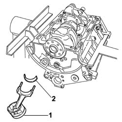
1. Remove the connecting rod-piston assemblies from the lower part of the crankcase.
2. Remove the connecting rod half-bearing.
- Work in the same way to remove the remaining connecting rod-piston assemblies on both sides.
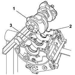
1. Remove the crankshaft.
2. Remove the main journal half-bearings.
3. Remove the thrust washers.
- Rotate the engine through 90° on the overhaul stand.
- Remove the timing side engine support.
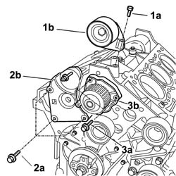
1. Undo the fixing bolts (1a) and remove the fixed timing belt tensioner (1b).
2. Undo the bolts (2a) and remove the moving timing belt tensioner support.
3. Undo the bolts (3a) and remove the crankshaft pulley (3b).
- Separate the water pump gasket.
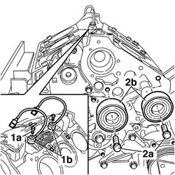
1. Undo the fixing bolts (1a) and remove the detonation sensors (1b).
2. Undo the bolts (2a) and remove the fixed timing belt tensioners (2b).
1. Undo the fixing bolt (1a) and remove the engine oil dipstick (1b).
2. Undo the fixing bolt (2a) and remove the engine oil temperature sensor (2b).
3. Undo and remove the engine oil pressure sensor.
1. Undo the retaining bolts (1a) and remove the air conditioning compressor (1b).
1. Undo the bolts (1a) and remove the air conditioning compressor support (1b) and support (1c).
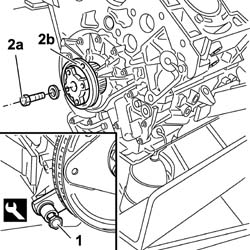
1. Fit the flywheel lock.
2. Undo the bolt (2a) and remove the timing belt toothed drive pulley (2b).
| Description | Code | Function | |
|---|---|---|---|
| 1 | Counter-torque | 1.860.846.000 |
1. Undo the fixing bolts (1a) and remove the crankshaft front oil seal cover with built-in oil pump (1b).
1. Undo the bolts (1a) and remove the engine flywheel (1b).
2. Remove the flywheel lock.
| Description | Code | Function | |
|---|---|---|---|
| 2 | Counter-torque | 1.860.846.000 |
1. Undo and remove the plugs (1a), then undo the bolts underneath (1b) fixing the the lower crankcase with a main bearing cap function.
2. Undo the remaining bolts fixing the lower crankcase to the upper crankcase.
Before dismantling the crankshaft, mark the position of the crankshaft bearings and the thrust washers to avoid refitting them incorrectly.
3. Separate the lower crankcase (3a) from the upper crankcase (3b) and place it on a special workbench.
4. Remove the lower main journal half-bearings.
5. Remove the crankshaft rear oil seal
Before dismanling the connecting rod-piston assemblies, mark the crankpins and the half-bearings to avoid refitting them incorrectly.
1. Undo the nuts (1a) and remove the connecting rod caps (1b) complete with half bearings (1c).
1. Remove the connecting rod-piston assemblies from the lower part of the crankcase.
2. Remove the connecting rod half-bearing.
- Work in the same way to remove the remaining connecting rod-piston assemblies on both sides.
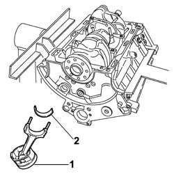
1. Remove the crankshaft.
2. Remove the main journal half-bearings.
3. Remove the thrust washers.
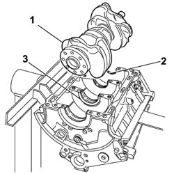
- Visually inspect the condition of the main journal and crankpin half-bearings and replace them if necessary.
- Clean the lubrication ports in the crankshaft using an air jet.
- Check the static balance of the crankshaft resting the main journals on suitable parallels.
- Check that the diameter of the main journals corresponds to the recommended figures.
| Main journal diameter (mm) | Validity | ||
|---|---|---|---|
| Category A | Category B | Category C | |
| - ÷ - | - ÷ - | - ÷ - | |
- If the diameter of the main journals is not correct, they should be reground to the recommended undersize.
Because the crankshaft has undergone nitriding, this treatment should be repeated and the size re-checked if it is ground.
| Main journal undersize (mm) | Validity |
|---|
- Check that the diameter of the crankpins corresponds to the recommended figures.
| Crankpin diameter (mm) | Validity |
|---|---|
| - ÷ - |
- If the diameter of the crankpins is not correct, they should be reground to the recommended undersize.
Because the crankshaft has undergone nitriding, this treatment should be repeated and the size re-checked if it is ground.
| Crankpin undersize (mm) | Validity |
|---|
Carry out
Op. 1028H54 PISTON/CYLINDER LINER - R R
- Clean any carbon residues carefully from the pistons.
- Check that the outer diameter of the pistons corresponds to the recommended figures; if not, replace the piston complete with piston rings and gudgeon pin.
| Outer diameter (mm) | Validity | ||
|---|---|---|---|
| Category A | Category B | Category C | |
| 86.975 ÷ 86.982 | 86.982 ÷ 86.989 | 86.989 ÷ 86.996 | |
- Position the piston in the cylinder liner and user a feeler gauge to measure the specified clearance.
| Clearance between piston - cylinder liner (mm) | Validity |
|---|---|
| - ÷ - |
- Check that the pin seat bore diameter is within specified values, otherwise replace the pin with an oversized pin.
| Piston pin housing diameter (mm) | Validity |
|---|---|
| - ÷ - |
| Pin oversize (mm) | Validity |
|---|
- Check that the outer diameter of the piston pins corresponds to the recommended figures; if not, replace the worn components.
| Piston pin outer diameter (mm) | Validity |
|---|---|
| - ÷ - |
- Use a micrometer gauge to measure the thickness of the piston sealing rings.
| Thickness (mm) | Validity | |||
|---|---|---|---|---|
| 1st sealing ring | 2nd sealing ring | 3rd sealing ring | Sealing ring oversize | |
| - ÷ - | - ÷ - | - ÷ - | ||
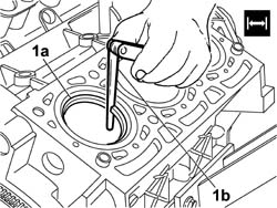
1. Fit the sealing rings (1a) in the cylinder liner and use a feeler gauge (1b) to check the gap between the seal ends is within specified limits. Otherwise replace the sealing rings.
| Gap (mm) | Validity | ||
|---|---|---|---|
| 1st sealing ring | 2nd sealing ring | 3rd sealing ring | |
| - ÷ - | - ÷ - | - ÷ - | |
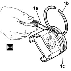
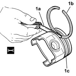
1. Use a feeler gauge (1a) to check the mating clearance between the retaining rings (1b) and the grooves on the piston (1c).
| End float (mm) | Validity | ||
|---|---|---|---|
| 1st sealing ring | 2nd sealing ring | 3rd sealing ring | |
| - ÷ - | - ÷ - | - ÷ - | |
- Check that the small end bush bore diameter is within the recommended limits; if not, replace the connecting rod.
- Fit the caps on the connecting rods and secure them tightening the nuts to the recommended torque.
| Value daNm | Fastening | Component | Ø | |
|---|---|---|---|---|
| 2 + 74° | Nut | CONNECTING ROD CAPS |
- Check that the diameter of the big end corresponds to the recommended figures. If this is not the case, replace the connecting rod.
Carry out
Op. 1028H60 PISTON, PIN SET - REPLACE
1. Fit the connecting rod-piston assemblies (1a) with half-bearings using tool (1b) to compress the piston rings and then fit the piston into the cylinder liner.
| Description | Code | Function | |
|---|---|---|---|
| 1b | Fitting tool | 1.860.700.000 | Fitting connecting rod-piston assemblies in cylinder liners/bores |
The pistons should be fitted with the arrows stamped on the crown facing the timing side. The numbers of the cylinder to which each piston belongs are stamped on the crankcase.
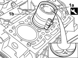
- Rotate the engine on the overhaul stand, taking care that the pistons do not come out of the bores.
- Check the main bearings, noting that the half-bearings should not be adapted. Replace them if scoring or signs of binding are noted.
- Fit the half-bearings in the housings in the upper crankcase making sure it is scrupulously clean. There are thrust washers by the centre half-bearing.
- If the crankshaft has been ground, fit new oversize half-bearings to restore the initial tolerance conditions.
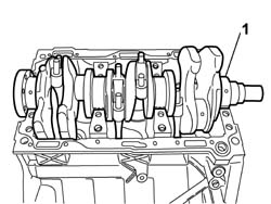
1. Fit the crankshaft in the special housing in the upper crankcase taking care to fit the big end on each crankpin.
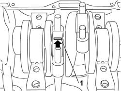
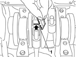
1. Apply the calibrated wire (plastigate) for measuring the crankpin clearance.
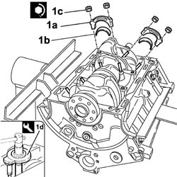
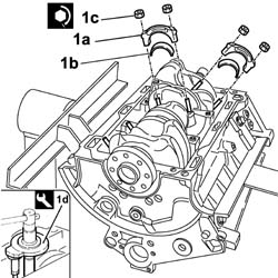
1. Fit the connecting rod caps (1a) complete with half-bearings (1b) and secure by tightening the nuts (1c) to the specified torque using tool (1d) for angular tightening.
The caps are fitted with the stamps facing the same side as those on the big ends.
| Value daNm | Fastening | Component | Ø | |
|---|---|---|---|---|
| 1c | 2 + 74° | Nut | CONNECTING ROD CAPS |
| Description | Code | Function | |
|---|---|---|---|
| 1d | Torque wrench | 1.860.942.000 | Angular tightening of bearing cap bolts |
1. Remove the connecting rod caps and check the crankpin clearance. Use an appropriate gauge to measure the width of the plastigage.
Check one crankpin at a time, without rotating the crankshaft.
| Clearance between connectring rod bearings - crankpins (mm) | Validity |
|---|---|
| - ÷ - |
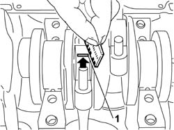
- If the value measured is not within the recommended figures, replace the connecting rod bearings.
- Refit the connecting rod caps complete with half-bearings and secure them by tightening the bolts to the recommended torque.
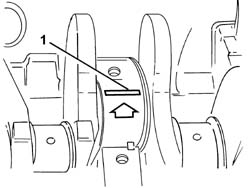
1. Fit the calibrated wire (plastigage) for measuring the bearing clearance.
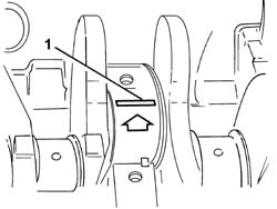
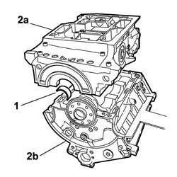
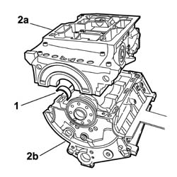
1. Fit the main journal half-bearings in the lower cylinder block/crankcase.
2. Fit the lower crankcase (2a) on the upper one (2b).
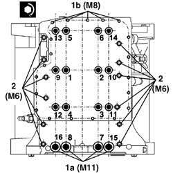
Tighten the lower crankcase fixing bolts, following the procedure described below bearing in mind that the tightening order illustrated in the diagram should be followed for each stage.
1. Tighten the M11 bolts (1a) and the M8 bolts (1b) to the pre-torque given in the table.
| Value (daNm) | Fastening | Components | Ø | |
|---|---|---|---|---|
| (Lower crankcase - pre-torque) 3 | Bolt | Lower crankcase - pre-torque | M11 |
| Value (daNm) | Fastening | Components | Ø | |
|---|---|---|---|---|
| (Lower crankcase - pre-torque) 1 | Bolt | Lower crankcase - pre-torque | M8 |
2. Tighten the M6 bolts to the recommended torque.
| Value (daNm) | Fastening | Components | Ø | |
|---|---|---|---|---|
| 2 | (Lower crankcase) 1 | Bolt | Lower crankcase | M6 |
- Undo the M11 and M8 bolts until the torque applied previously is cancelled.
- Tighten the M8 and M11 bolts tightening the lower crankcase to the upper crankcase definitively to the recommended torque following the order illustrated in the diagram; use the special tool for the angular tightening.
| Value (daNm) | Fastening | Components | Ø | |
|---|---|---|---|---|
| (Lower crankcase) 3+180° | Bolt | Cylinder block/crankcase | M11 |
| Value (daNm) | Fastening | Components | Ø | |
|---|---|---|---|---|
| (Lower crankcase) 1+180° | Bolt | Cylinder block/crankcase | M8 |
| Description | Code | Function | |
|---|---|---|---|
| Torque wrench | 1.860.942.000 | Angular tightening of bearing cap bolts |
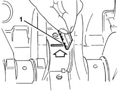
1. Remove the lower crankcase and check the crankpin clearance. Use an appropriate gauge to measure the width of the plastigage.
Check one main journal at a time, without rotating the crankshaft.
| Clearance between main bearings - crankshaft main journals (mm) | Validity |
|---|---|
| - ÷ - |
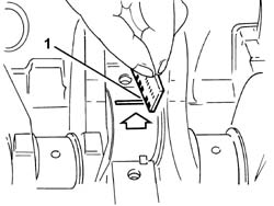
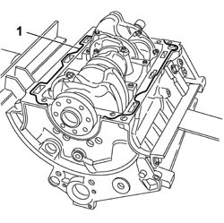
1. After checking all the main journals, apply sealant continuously along the splining on the upper crankcase, then fit the lower crankcase permanently by tightening the bolts to torque in the order described previously.
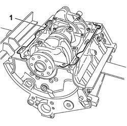
Carry out
Op. 1084B18 ENGINE OIL PUMP, REMOVED - CHECK AT BENCH
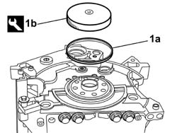
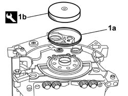
1. Fit the flywheel side oil seal (1a) using the tool (1b).
| Description | Code | Function | |
|---|---|---|---|
| 1b | Tool for fitting oil seal | 1.870.895.000 | Fitting flywheel side oil seal |
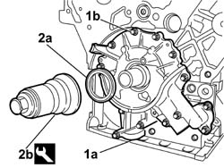
1. Position the crankcase front cover with built-in oil pump (1a) and screw in the fixing bolts (1b) without tightening them.
2. Fit the oil seal (2a) using the tool (2b).
| Description | Code | Function | |
|---|---|---|---|
| 2b | Fitting tool | 1.870.896.000 | Tool for fitting (timing side) crankshaft oil seal |
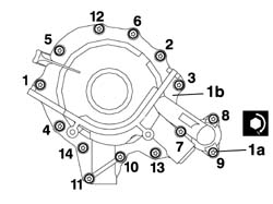
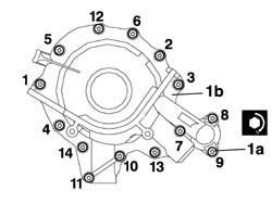
1. Tighten the bolts (1a) fixing the crankcase front cover with built-in oil pump (1b) following the procedure described below and following the tightening order illustrated for each stage.
- Pre-tighten the oil pump fixing bolts to the value given in the table.
| Value (daNm) | Fastening | Components | Ø | |
|---|---|---|---|---|
| pre-tightening 0.5 | Bolt | ENGINE OIL PUMP | M |
- Tighten the bolts fixing the oil pump to the recommended torque.
| Value (daNm) | Fastening | Components | Ø | |
|---|---|---|---|---|
| 0.8 | Bolt | ENGINE OIL PUMP | M |
- Carry out the tightening several times following the order given until each bolt is at the recommended torque.
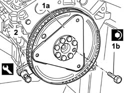
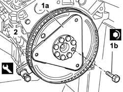
Apply FRENETANCH thread-locking agent, or a similar product, to the engine flywheel fixing bolts.
1. Fit the engine flywheel (1a) and secure it without tightening the bolts (1b).
2. Fit the flywheel lock.
| Description | Code | Function | |
|---|---|---|---|
| 2 | Counter-torque | 1.860.846.000 |
- Tighten the flywheel bolts to the recommended torque.
| Value (daNm) | Components | Fastening | Ø | |
|---|---|---|---|---|
| 1b | 2 + 60° | FLYWHEEL MECH. | Bolt | M |
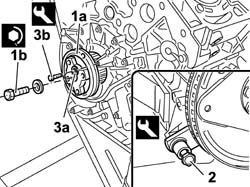
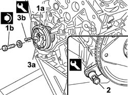
Apply FRENETANCH thread-locking agent, or a similar product, to the auxiliary drive pulley fixing bolts.
1. Fit the drive pulley (1a) complete with gear on the crankshaft, then tighten the fixing bolt (1b) to the recommended torque with the flywheel lock fitted.
| Value (daNm) | Components | Fastening | Ø | |
|---|---|---|---|---|
| 1b | 4 + 80° | DRIVE PULLEY(PULLIES) TIMING | Bolt | M |
2. Remove the flywheel lock.
3. Rotate the crankshaft to align the opening (3a) in the drive pulley with the opening in the cylinder block/crankcase, then insert the shaft timing tool (3b).
| Description | Code | Function | |
|---|---|---|---|
| 2 | Counter-torque | 1.860.846.000 |
| Description | Code | Function | |
|---|---|---|---|
| 3b | Pins | 1.870.893.000 | Reaction pins for timing pullies |
- Position the partition and tighten the bolts fixing it to the lower crankcase.
- Position the suction pump inside the monobloc and tighten the bolts fixing it to the lower crankcase.
- Clean the crankcase and oil sump contact surfaces, removing the silicon sealant residues.
- Apply the specified sealant continuously without any breaks over the entire perimeter of the crankcase sump.
Join the end to the beginning seamlessly.
| Component | Type | Description | Classification | Qty. | Validity |
|---|---|---|---|---|---|
| ENGINE OIL SUMP | Silicon sealant | LOCTITE 5900 |
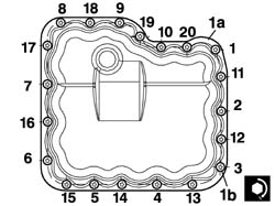
1. Positin the crankcase sump (1a) and tighten the fixing bolts (1b) following the procedure described below and following the order illustrated for each tightening stage.
- Tighten the bolts marked in the diagram with the numbers 13, 15, 17.
- Tighten the bolts in the diagram marked with the numbers 13, 15, 17 to a torque of 0.2 daNm.
- Tighten the remaining seventeen bolts.
- Tighten the remaining seventeen bolts to a torque of 0.5 daNm following the order illustrated in the diagram.
- Tighten all the oil sump fixing bolts to the recommended torque following the order illustrated.
| Value (daNm) | Components | Fastening | Ø | |
|---|---|---|---|---|
| 1b | 0.8 | ENGINE OIL SUMP | Bolt | M6 |
- Rotate the engine on the rotating stand.
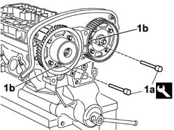
1. Before fitting the cylinder head on the engine block, the timing pullies must be locked in the timing position. Rotate the camshafts, inert the retaining tools (1a) in the special housings in the pullies (1b) in the position illustrated in the diagram.
| Description | Code | Function | |
|---|---|---|---|
| 1a | Pins | 1.870.893.000 | Reaction pins for timing pullies |
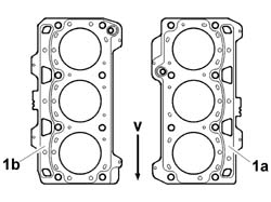
Multi-layer type cylinder head gaskets are fitted. If the cylinder head is refaced to a maximum value of 0.2 mm, use a 0.95 mm oversize cylinder head gasket.
1. Position the gasket on the cylinder block/crankcase, taking care not to get the gasket or the surface of the cylinder block/crankcase dirty or covered in oil. The gasket (1a) for the right head and the gasket (1b) for the left head are illustrated in the diagram. The reference (V) represents the flywheel side.
- Position the cylinder head on the crankcase inserting it on the locating pins.
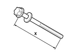
1. Before reusing the cylinder head fixing bolts, check that they are not longer than X = 149.5 mm, if this is not the case, replace the bolts with new ones.
- Clean any residues of sealant from the openings in the cylinder block/crankcase using an M10 X 1.5 bolt.
- Brush the thread of the head bolts.
- Position the head bolts after having applied grease to the thread and under the head.
| Component | Type | Description | Classification | Qty. | Validity |
|---|---|---|---|---|---|
| CYLINDER HEAD GASKET | GREASE | MOLYKOTE GRAPID PLUS |
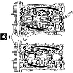
1. Tighten the cylinder head fixing bolts, following the procedure described below bearing in mind that the tightening order illustrated in the diagram should be followed for each stage.
- Pre-tighten the cylinder head fixing bolts to the value given in the table.
| Value (daNm) | Components | Fastening | Ø | |
|---|---|---|---|---|
| 2.0 | CYLINDER HEAD EXT FASTENERS | Bolt | M |
- Undo the bolts until the torque applied previously is cancelled.
- Tighten the cylinder head fixing bolts definitively to the recommended torque following the order illustrated in the diagram; use the special tool for the angular tightening.
| Value (daNm) | Components | Fastening | Ø | |
|---|---|---|---|---|
| 1.5 + 225° | CYLINDER HEAD EXT FASTENERS | Bolt | M |
| Description | Code | Function | |
|---|---|---|---|
| Torque wrench | 1.860.942.000 | Angular tightening of lower crankcase bolts |
- Fit the engine oil level sensor and tighten the bolt fixing it to the lower crankcase.
- Fit the engine oil pressure sensor and tighten it to the lower crankcase.
- Position the air conditioning compressor supports and tighten the bolts fixing them to the lower crankcase.
- Position the air conditioning compressor and tighten the bolts fixing it to the lower crankcase.
- Position the engine oil dipstick, then tighten the fixing bolt.
- Position the heat exchanger and tighten it to the lower crankcase.
- Tighten the oil filter to the heat exchanger.
- Fit the seal on the water pump casing.
- Position the water pump and screw in the fixing bolts without tightening them.
1. Tighten the water pump fixing bolts, following the procedure described below bearing in mind that the tightening order illustrated in the diagram should be followed for each stage.
- Pre-tighten the cylinder head fixing bolts to the value given in the table.
| Value (daNm) | Components | Fastening | Ø | |
|---|---|---|---|---|
| 0.5 | COOLANT PUMP | Bolt | M |
- Tighten the bolts fixing the water pump permanently to the recommended torque.
| Value (daNm) | Components | Fastening | Ø | |
|---|---|---|---|---|
| 0.8 | COOLANT PUMP | Bolt | M |
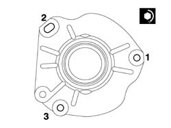
- Position the detonation sensors on the engine block and tighten the fixing bolts.
- Position the timing belt fixed tensioners and tighten the bolts fixing them to the engine block.
- Position the engine support and tighten the bolts fixing it to the upper crankcase to torque.
| Value (daNm) | Components | Fastening | Ø | |
|---|---|---|---|---|
| (Cylinder guard side) 6 | INTERMEDIATE RIGID SUPPORT | Bolt | M |
- Position the timing belt fixed tensioner support and tighten the bolts fixing it to the upper crankcase.
- Fit the fixed timing belt tensioner and tighten the fixing bolt to the recommended torque.
| Value (daNm) | Components | Fastening | Ø | |
|---|---|---|---|---|
| (Cylinder head) 8 | FIXED TENSIONER | Bolt | M |
- Position the timing belt moving tensioner support and tighten the bolts fixing it to the crankcase.
- Fit the moving tensioner and tighten the fixing nut.
Make sure that the camshaft pulley retaining tools are correctly inserted in the special housings and that there is a pin in the crankshaft pulley housing.
1. Check that the rollers (1a) and the water pump (1b) rotate freely and there is no clearance or hard spots.
2. Loosen the bolts fixing the camshaft pullies.
Make sure that the camshaft and crankshaft calibration is correct.
Check that the camshaft pinions rotate freely on their hub.
- Rotate the camshaft pullies in a clockwise direction until the tappets stop at the bottom.
- Fit the timing belt on the crankshaft pulley.
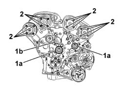
1. Position the timing belt on the fixed tensioner (1a), then make sure that the branch (1b) of the belt is taut.
Gently rotate the camshaft pulley in the opposite direction of rotation to the direction of rotation of the engine to facilitate the fitting of the timing belt.
2. Fit the timing belt on the camshaft exhaust pulley.
The value of the angular movement of the pulley in relation to the timing belt should not exceed the width of one tooth.
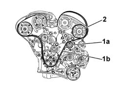
1. Fit the timing belt on the camshaft inlet pulley.
2. Position the roller on the engine and tighten the fixing bolt to the recommended torque.
| Value (daNm) | Components | Fastening | Ø | |
|---|---|---|---|---|
| 8 | FIXED TENSIONER | Bolt |
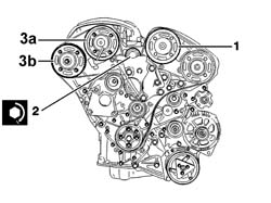
3. Fit the timing belt on the inlet pulley (3a) and on the exhaust pulley (3b).
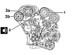
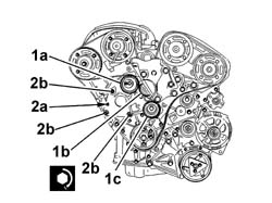
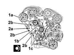
1. Fit the timing belt on the moving tensioner (1a), on the water pump pulley (1b) and on the fixed tensioner (1c).
2. Exerting a counter-force through the opening (2a) in the moving tensioner support, fit the bolts (2b) and tighten them to the recommended torque.
| Value (daNm) | Components | Fastening | Ø | |
|---|---|---|---|---|
| 2.5 | MOBILE TIMING TENSIONER | Bolts |
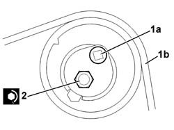
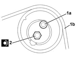
1. Exert a counter-force through the opening (1a) and tension the timing belt (1b) rotating the tensioner roller in an anti-clockwise direction until it is in the end of travel position.
2. Tighten the nut on the timing belt moving tensioner to the recommended torque.
| Value (daNm) | Components | Fastening | Ø | |
|---|---|---|---|---|
| 2 | 1 | MOVING TENSIONER | Bolts |
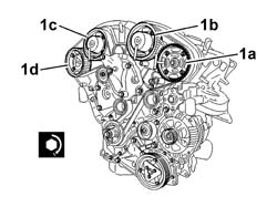
1. Tighten the bolts (1a), (1b), (1c) and (1d) fixing the camshaft pullies to the recommended torque following the order illustrated in the diagram.
| Value (daNm) | Components | Fastening | Ø | |
|---|---|---|---|---|
| 1a | 1 | DRIVE PULLEY(PULLIES) TIMING | Bolts |
| Value (daNm) | Components | Fastening | Ø | |
|---|---|---|---|---|
| 1b | 1 | DRIVE PULLEY(PULLIES) TIMING | Bolts |
| Value (daNm) | Components | Fastening | Ø | |
|---|---|---|---|---|
| 1c | 1 | DRIVE PULLEY(PULLIES) TIMING | Bolts |
| Value (daNm) | Components | Fastening | Ø | |
|---|---|---|---|---|
| 1d | 1 | DRIVE PULLEY(PULLIES) TIMING | Bolts |
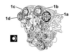
Before completing two revolutions of the crankshaft, make sure that the timing pins slide freely in the housings in the camshaft pullies. If this is not the case, loosen the bolts fixing the camshaft pullies, then position the drive pulley so that the timing pins can be extracted. Tighten to torque taking care to start with the bolt furthest away from the timing pin.
- Remove the timing pulley retaining tools.
| Description | Code | Function | |
|---|---|---|---|
| Pins | 1.870.893.000 | Reaction pins for timing pullies |
- Rotate the crankshaft throught two revolutions in its normal direction of rotation.
Never rotate in the opposite direction to the normal one.
- Position the retaining tool on the crankshaft pulley only.
| Description | Code | Function | |
|---|---|---|---|
| Pins | 1.870.893.000 | Reaction pins for timing pullies |
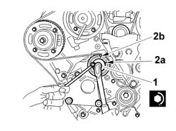
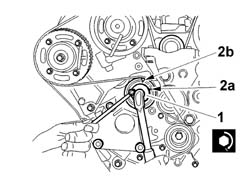
1. Loosen the nut retaining the timing belt moving tensioner.
2. Align the tensioner roller references (2a) and (2b).
- Tighten the nut on the timing belt moving tensioner loosened previously.
| Value (daNm) | Components | Fastening | Ø | |
|---|---|---|---|---|
| 1 | 2.5 | MOVING TENSIONER | Bolts |
- Remove the retaining tool from the crankshaft pulley.
| Description | Code | Function | |
|---|---|---|---|
| Pins | 1.870.893.000 | Reaction pins for timing pullies |
- Rotate the crankshaft throught two revolutions in its normal direction of rotation.
Never rotate in the opposite direction to the normal one.
- Check the position of the timing belt moving tensioner.
If the references on the timing belt tensioner roller were not aligned, repeat the operation of fitting the belt.
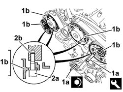
1. Fit the retaining tools (1a) in the special housings in the timing pullies (1b).
| Description | Code | Function | |
|---|---|---|---|
| 1a | Pins | 1.870.893.000 | Reaction pins for timing pullies |
2. Check that the references (2a) for the adjustment of the camshafts engage freely in the heads (2b) until they are in contact with the camshaft pinions.
If this is not the case, start the operation of fitting the belt again.
- Remove the timing pulley retaining tools.
| Description | Code | Function | |
|---|---|---|---|
| Pins | 1.870.893.000 | Reaction pins for timing pullies |
Apply FRENETANCH thread-locking agent, or a similar product, to the auxiliary drive pulley fixing bolts.
- Tighten the bolts fixing the auxiliary drive pulley to the recommended torque.
| Value (daNm) | Components | Fastening | Ø | |
|---|---|---|---|---|
| 2.5 | CRANKSHAFT PULLEY | Bolt | M8 |
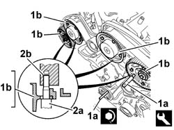
- Position the timing or cam angle sensors for the front head and the rear head, then tighten the fixing bolts.
- Position the front head and rear head phase transformer sensors and tighten the fixing bolts.
- Position the intake manifold gaskets on the cylinder heads.
- Position the intake manifold and tighten the fixing nuts.
- Position the fuel manifolds on the front and rear heads, then tighten the fixing bolts.
- Fit the ignition coils for the cylinder heads in their housings.
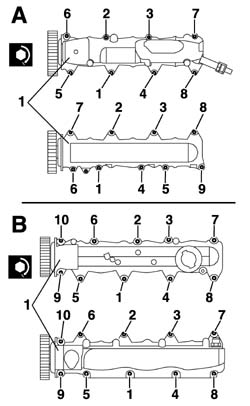
- Fit the tappet covers on the cylinder heads.
The tappet covers have a composite seal which can be removed and refitted several times. If the gasket is torn, it can be partly repaired using SILICONE CATEGORIE 2 special compound.
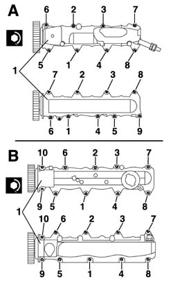
1. Tighten the tappet cover fixing bolts, following the procedure described below bearing in mind that the tightening order illustrated in the diagram should be followed for each stage.
- Pre-tighten the tappet cover fixing bolts to the value given in the table.
| Value (daNm) | Components | Fastening | Ø | |
|---|---|---|---|---|
| 0.5 | TAPPET COVERS | Bolt | M |
- Tighten the bolts fixing the tappet covers permanently to the recommended torque.
| Value (daNm) | Components | Fastening | Ø | |
|---|---|---|---|---|
| 0.8 | TAPPET COVERS | Bolt | M |
- Connect the electrical connections for the ignition coils and the electrical connection for the phase transformer actuator.
| Description | Connector | |
|---|---|---|
| Ignition coils | See A030 Ignition coil |
| Description | Connector | |
|---|---|---|
| Phase transformer solenoid valve | See N076 |
| Description | Connector | |
|---|---|---|
| Phase transformer solenoid valve | See N076 PHASE TRANSFORMER ACTUATOR |
- Positionthe electrical connection for the engine cable loom coupling on the tappet cover and tighten the fixing bolt.
- Connect the electrical connections for the cylinder position reference sensors.
| Description | Connector | |
|---|---|---|
| 1 | Cylinder reference sensor | See K168 |
| Description | Connector | |
|---|---|---|
| 2 | Cylinder reference sensor | See K169 CYLINDER REFERENCE SENSOR -2 |
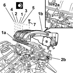
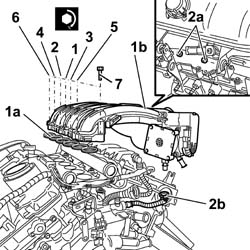
1. Position the gasket (1a) for the intake chamber on the inlet ducts. Tighten the intake chamber (1b) fixing bolts, following the procedure described below bearing in mind that the tightening order illustrated in the diagram should be followed for each stage.
- Pre-tighten the intake chamber fixing bolts to the value given in the table.
| Value (daNm) | Components | Fastening | Ø | |
|---|---|---|---|---|
| 0.4 | INLET AIR DUCT | Bolt | M |
- Tighten the bolts fixing the intake chamber permanently to the recommended torque.
| Value (daNm) | Components | Fastening | Ø | |
|---|---|---|---|---|
| 0.8 | INLET AIR DUCT | Bolt | M |
2. Tighten the nuts (2a) fixing the intake chamber, then connect the oil vapour recovery pipe (2b) to the throttle casing.
Complete with
Op. 1004D40 ENGINE - POSITION ON STAND AND REMOVE
- Visually inspect the condition of the main journal and crankpin half-bearings and replace them if necessary.
- Clean the lubrication ports in the crankshaft using an air jet.
- Check the static balance of the crankshaft resting the main journals on suitable parallels.
- Check that the diameter of the main journals corresponds to the recommended figures.
| Main journal diameter (mm) | Validity | ||
|---|---|---|---|
| Category A | Category B | Category C | |
| - ÷ - | - ÷ - | - ÷ - | |
- If the diameter of the main journals is not correct, they should be reground to the recommended undersize.
Because the crankshaft has undergone nitriding, this treatment should be repeated and the size re-checked if it is ground.
| Main journal undersize (mm) | Validity |
|---|
- Check that the diameter of the crankpins corresponds to the recommended figures.
| Crankpin diameter (mm) | Validity |
|---|---|
| - ÷ - |
- If the diameter of the crankpins is not correct, they should be reground to the recommended undersize.
Because the crankshaft has undergone nitriding, this treatment should be repeated and the size re-checked if it is ground.
| Crankpin undersize (mm) | Validity |
|---|
Carry out
Op. 1028H54 PISTON/CYLINDER LINER - R R
- Clean any carbon residues carefully from the pistons.
- Check that the outer diameter of the pistons corresponds to the recommended figures; if not, replace the piston complete with piston rings and gudgeon pin.
| Outer diameter (mm) | Validity | ||
|---|---|---|---|
| Category A | Category B | Category C | |
| 86.975 ÷ 86.982 | 86.982 ÷ 86.989 | 86.989 ÷ 86.996 | |
- Position the piston in the cylinder liner and user a feeler gauge to measure the specified clearance.
| Clearance between piston - cylinder liner (mm) | Validity |
|---|---|
| - ÷ - |
- Check that the pin seat bore diameter is within specified values, otherwise replace the pin with an oversized pin.
| Piston pin housing diameter (mm) | Validity |
|---|---|
| - ÷ - |
| Pin oversize (mm) | Validity |
|---|
- Check that the outer diameter of the piston pins corresponds to the recommended figures; if not, replace the worn components.
| Piston pin outer diameter (mm) | Validity |
|---|---|
| - ÷ - |
- Use a micrometer gauge to measure the thickness of the piston sealing rings.
| Thickness (mm) | Validity | |||
|---|---|---|---|---|
| 1st sealing ring | 2nd sealing ring | 3rd sealing ring | Sealing ring oversize | |
| - ÷ - | - ÷ - | - ÷ - | ||
1. Fit the sealing rings (1a) in the cylinder liner and use a feeler gauge (1b) to check the gap between the seal ends is within specified limits. Otherwise replace the sealing rings.
| Gap (mm) | Validity | ||
|---|---|---|---|
| 1st sealing ring | 2nd sealing ring | 3rd sealing ring | |
| - ÷ - | - ÷ - | - ÷ - | |
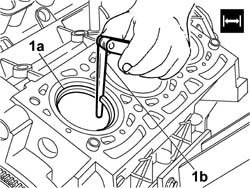
1. Use a feeler gauge (1a) to check the mating clearance between the retaining rings (1b) and the grooves on the piston (1c).
| End float (mm) | Validity | ||
|---|---|---|---|
| 1st sealing ring | 2nd sealing ring | 3rd sealing ring | |
| - ÷ - | - ÷ - | - ÷ - | |
- Check that the small end bush bore diameter is within the recommended limits; if not, replace the connecting rod.
- Fit the caps on the connecting rods and secure them tightening the nuts to the recommended torque.
| Value daNm | Fastening | Component | Ø | |
|---|---|---|---|---|
| 2 + 74° | Nut | CONNECTING ROD CAPS |
- Check that the diameter of the big end corresponds to the recommended figures. If this is not the case, replace the connecting rod.
Carry out
Op. 1028H60 PISTON, PIN SET - REPLACE
1. Fit the connecting rod-piston assemblies (1a) with half-bearings using tool (1b) to compress the piston rings and then fit the piston into the cylinder liner.
| Description | Code | Function | |
|---|---|---|---|
| 1b | Fitting tool | 1.860.700.000 | Fitting connecting rod-piston assemblies in cylinder liners/bores |
The pistons should be fitted with the arrows stamped on the crown facing the timing side. The numbers of the cylinder to which each piston belongs are stamped on the crankcase.
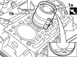
- Rotate the engine on the overhaul stand, taking care that the pistons do not come out of the bores.
- Check the main bearings, noting that the half-bearings should not be adapted. Replace them if scoring or signs of binding are noted.
- Fit the half-bearings in the housings in the upper crankcase making sure it is scrupulously clean. There are thrust washers by the centre half-bearing.
- If the crankshaft has been ground, fit new oversize half-bearings to restore the initial tolerance conditions.
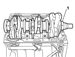
1. Fit the crankshaft in the special housing in the upper crankcase taking care to fit the big end on each crankpin.
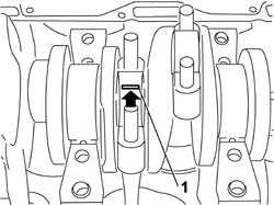
1. Apply the calibrated wire (plastigate) for measuring the crankpin clearance.
1. Fit the connecting rod caps (1a) complete with half-bearings (1b) and secure by tightening the nuts (1c) to the specified torque using tool (1d) for angular tightening.
The caps are fitted with the stamps facing the same side as those on the big ends.
| Value daNm | Fastening | Component | Ø | |
|---|---|---|---|---|
| 1c | 2 + 74° | Nut | CONNECTING ROD CAPS |
| Description | Code | Function | |
|---|---|---|---|
| 1d | Torque wrench | 1.860.942.000 | Angular tightening of bearing cap bolts |
1. Remove the connecting rod caps and check the crankpin clearance. Use an appropriate gauge to measure the width of the plastigage.
Check one crankpin at a time, without rotating the crankshaft.
| Clearance between connectring rod bearings - crankpins (mm) | Validity |
|---|---|
| - ÷ - |
- If the value measured is not within the recommended figures, replace the connecting rod bearings.
- Refit the connecting rod caps complete with half-bearings and secure them by tightening the bolts to the recommended torque.
1. Fit the calibrated wire (plastigage) for measuring the bearing clearance.
1. Fit the main journal half-bearings in the lower cylinder block/crankcase.
2. Fit the lower crankcase (2a) on the upper one (2b).
Tighten the lower crankcase fixing bolts, following the procedure described below bearing in mind that the tightening order illustrated in the diagram should be followed for each stage.
1. Tighten the M11 bolts (1a) and the M8 bolts (1b) to the pre-torque given in the table.
| Value (daNm) | Fastening | Components | Ø | |
|---|---|---|---|---|
| (Lower crankcase - pre-torque) 3 | Bolt | Lower crankcase - pre-torque | M11 |
2. Tighten the M6 bolts to the recommended torque.
| Value (daNm) | Fastening | Components | Ø | |
|---|---|---|---|---|
| 2 | (Lower crankcase) 1 | Bolt | Lower crankcase | M6 |
- Undo the M11 and M8 bolts until the torque applied previously is cancelled.
- Tighten the M8 and M11 bolts tightening the lower crankcase to the upper crankcase definitively to the recommended torque following the order illustrated in the diagram; use the special tool for the angular tightening.
| Value (daNm) | Fastening | Components | Ø | |
|---|---|---|---|---|
| (Lower crankcase) 3+180° | Bolt | Cylinder block/crankcase | M11 |
| Value (daNm) | Fastening | Components | Ø | |
|---|---|---|---|---|
| (Lower crankcase) 1+180° | Bolt | Cylinder block/crankcase | M8 |
| Description | Code | Function | |
|---|---|---|---|
| Torque wrench | 1.860.942.000 | Angular tightening of bearing cap bolts |
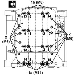
1. Remove the lower crankcase and check the crankpin clearance. Use an appropriate gauge to measure the width of the plastigage.
Check one main journal at a time, without rotating the crankshaft.
| Clearance between main bearings - crankshaft main journals (mm) | Validity |
|---|---|
| - ÷ - |
1. After checking all the main journals, apply sealant continuously along the splining on the upper crankcase, then fit the lower crankcase permanently by tightening the bolts to torque in the order described previously.
Carry out
Op. 1084B18 ENGINE OIL PUMP, REMOVED - CHECK AT BENCH
1. Fit the flywheel side oil seal (1a) using the tool (1b).
| Description | Code | Function | |
|---|---|---|---|
| 1b | Tool for fitting oil seal | 1.870.895.000 | Fitting flywheel side oil seal |
1. Position the crankcase front cover with built-in oil pump (1a) and screw in the fixing bolts (1b) without tightening them.
2. Fit the oil seal (2a) using the tool (2b).
| Description | Code | Function | |
|---|---|---|---|
| 2b | Fitting tool | 1.870.896.000 | Tool for fitting (timing side) crankshaft oil seal |
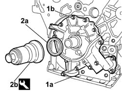
1. Tighten the bolts (1a) fixing the crankcase front cover with built-in oil pump (1b) following the procedure described below and following the tightening order illustrated for each stage.
- Pre-tighten the oil pump fixing bolts to the value given in the table.
| Value (daNm) | Fastening | Components | Ø | |
|---|---|---|---|---|
| pre-tightening 0.5 | Bolt | ENGINE OIL PUMP | M |
- Tighten the bolts fixing the oil pump to the recommended torque.
| Value (daNm) | Fastening | Components | Ø | |
|---|---|---|---|---|
| 0.8 | Bolt | ENGINE OIL PUMP | M |
- Carry out the tightening several times following the order given until each bolt is at the recommended torque.
Apply FRENETANCH thread-locking agent, or a similar product, to the engine flywheel fixing bolts.
1. Fit the engine flywheel (1a) and secure it without tightening the bolts (1b).
2. Fit the flywheel lock.
| Description | Code | Function | |
|---|---|---|---|
| 2 | Counter-torque | 1.860.846.000 |
- Tighten the flywheel bolts to the recommended torque.
| Value (daNm) | Components | Fastening | Ø | |
|---|---|---|---|---|
| 1b | 2 + 60° | FLYWHEEL MECH. | Bolt | M |
Apply FRENETANCH thread-locking agent, or a similar product, to the auxiliary drive pulley fixing bolts.
1. Fit the drive pulley (1a) complete with gear on the crankshaft, then tighten the fixing bolt (1b) to the recommended torque with the flywheel lock fitted.
| Value (daNm) | Components | Fastening | Ø | |
|---|---|---|---|---|
| 1b | 4 + 80° | DRIVE PULLEY(PULLIES) TIMING | Bolt | M |
2. Remove the flywheel lock.
3. Rotate the crankshaft to align the opening (3a) in the drive pulley with the opening in the cylinder block/crankcase, then insert the shaft timing tool (3b).
| Description | Code | Function | |
|---|---|---|---|
| 2 | Counter-torque | 1.860.846.000 |
| Description | Code | Function | |
|---|---|---|---|
| 3b | Pins | 1.870.893.000 | Reaction pins for timing pullies |
- Position the partition and tighten the bolts fixing it to the lower crankcase.
- Position the suction pump inside the monobloc and tighten the bolts fixing it to the lower crankcase.
- Clean the crankcase and oil sump contact surfaces, removing the silicon sealant residues.
- Apply the specified sealant continuously without any breaks over the entire perimeter of the crankcase sump.
Join the end to the beginning seamlessly.
| Component | Type | Description | Classification | Qty. | Validity |
|---|---|---|---|---|---|
| ENGINE OIL SUMP | Silicon sealant | LOCTITE 5900 |
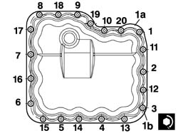
1. Positin the crankcase sump (1a) and tighten the fixing bolts (1b) following the procedure described below and following the order illustrated for each tightening stage.
- Tighten the bolts marked in the diagram with the numbers 13, 15, 17.
- Tighten the bolts in the diagram marked with the numbers 13, 15, 17 to a torque of 0.2 daNm.
- Tighten the remaining seventeen bolts.
- Tighten the remaining seventeen bolts to a torque of 0.5 daNm following the order illustrated in the diagram.
- Tighten all the oil sump fixing bolts to the recommended torque following the order illustrated.
| Value (daNm) | Components | Fastening | Ø | |
|---|---|---|---|---|
| 1b | 0.8 | ENGINE OIL SUMP | Bolt | M6 |
- Rotate the engine on the rotating stand.
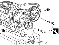
1. Before fitting the cylinder head on the engine block, the timing pullies must be locked in the timing position. Rotate the camshafts, inert the retaining tools (1a) in the special housings in the pullies (1b) in the position illustrated in the diagram.
| Description | Code | Function | |
|---|---|---|---|
| 1a | Pins | 1.870.893.000 | Reaction pins for timing pullies |
Multi-layer type cylinder head gaskets are fitted. If the cylinder head is refaced to a maximum value of 0.2 mm, use a 0.95 mm oversize cylinder head gasket.
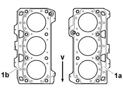
1. Position the gasket on the cylinder block/crankcase, taking care not to get the gasket or the surface of the cylinder block/crankcase dirty or covered in oil. The gasket (1a) for the right head and the gasket (1b) for the left head are illustrated in the diagram. The reference (V) represents the flywheel side.
- Position the cylinder head on the crankcase inserting it on the locating pins.
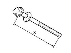
1. Before reusing the cylinder head fixing bolts, check that they are not longer than X = 149.5 mm, if this is not the case, replace the bolts with new ones.
- Clean any residues of sealant from the openings in the cylinder block/crankcase using an M10 X 1.5 bolt.
- Brush the thread of the head bolts.
- Position the head bolts after having applied grease to the thread and under the head.
| Component | Type | Description | Classification | Qty. | Validity |
|---|---|---|---|---|---|
| CYLINDER HEAD GASKET | GREASE | MOLYKOTE GRAPID PLUS |
1. Tighten the cylinder head fixing bolts, following the procedure described below bearing in mind that the tightening order illustrated in the diagram should be followed for each stage.
- Pre-tighten the cylinder head fixing bolts to the value given in the table.
| Value (daNm) | Components | Fastening | Ø | |
|---|---|---|---|---|
| 2.0 | CYLINDER HEAD EXT FASTENERS | Bolt | M |
- Undo the bolts until the torque applied previously is cancelled.
- Tighten the cylinder head fixing bolts definitively to the recommended torque following the order illustrated in the diagram; use the special tool for the angular tightening.
| Value (daNm) | Components | Fastening | Ø | |
|---|---|---|---|---|
| 1.5 + 225° | CYLINDER HEAD EXT FASTENERS | Bolt | M |
| Description | Code | Function | |
|---|---|---|---|
| Torque wrench | 1.860.942.000 | Angular tightening of lower crankcase bolts |
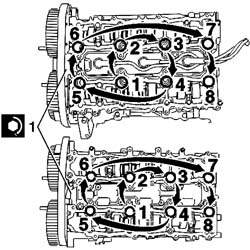
- Fit the engine oil level sensor and tighten the bolt fixing it to the lower crankcase.
- Fit the engine oil pressure sensor and tighten it to the lower crankcase.
- Position the air conditioning compressor supports and tighten the bolts fixing them to the lower crankcase.
- Position the air conditioning compressor and tighten the bolts fixing it to the lower crankcase.
- Position the engine oil dipstick, then tighten the fixing bolt.
- Position the heat exchanger and tighten it to the lower crankcase.
- Tighten the oil filter to the heat exchanger.
- Fit the seal on the water pump casing.
- Position the water pump and screw in the fixing bolts without tightening them.
1. Tighten the water pump fixing bolts, following the procedure described below bearing in mind that the tightening order illustrated in the diagram should be followed for each stage.
- Pre-tighten the cylinder head fixing bolts to the value given in the table.
| Value (daNm) | Components | Fastening | Ø | |
|---|---|---|---|---|
| 0.5 | COOLANT PUMP | Bolt | M |
- Tighten the bolts fixing the water pump permanently to the recommended torque.
| Value (daNm) | Components | Fastening | Ø | |
|---|---|---|---|---|
| 0.8 | COOLANT PUMP | Bolt | M |
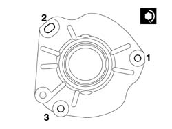
- Position the detonation sensors on the engine block and tighten the fixing bolts.
- Position the timing belt fixed tensioners and tighten the bolts fixing them to the engine block.
- Position the engine support and tighten the bolts fixing it to the upper crankcase to torque.
| Value (daNm) | Components | Fastening | Ø | |
|---|---|---|---|---|
| (Cylinder guard side) 6 | INTERMEDIATE RIGID SUPPORT | Bolt | M |
- Position the timing belt fixed tensioner support and tighten the bolts fixing it to the upper crankcase.
- Fit the fixed timing belt tensioner and tighten the fixing bolt to the recommended torque.
| Value (daNm) | Components | Fastening | Ø | |
|---|---|---|---|---|
| (Cylinder head) 8 | FIXED TENSIONER | Bolt | M |
- Position the timing belt moving tensioner support and tighten the bolts fixing it to the crankcase.
- Fit the moving tensioner and tighten the fixing nut.
Make sure that the camshaft pulley retaining tools are correctly inserted in the special housings and that there is a pin in the crankshaft pulley housing.
1. Check that the rollers (1a) and the water pump (1b) rotate freely and there is no clearance or hard spots.
2. Loosen the bolts fixing the camshaft pullies.
Make sure that the camshaft and crankshaft calibration is correct.
Check that the camshaft pinions rotate freely on their hub.
- Rotate the camshaft pullies in a clockwise direction until the tappets stop at the bottom.
- Fit the timing belt on the crankshaft pulley.
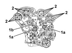
1. Position the timing belt on the fixed tensioner (1a), then make sure that the branch (1b) of the belt is taut.
Gently rotate the camshaft pulley in the opposite direction of rotation to the direction of rotation of the engine to facilitate the fitting of the timing belt.
2. Fit the timing belt on the camshaft exhaust pulley.
The value of the angular movement of the pulley in relation to the timing belt should not exceed the width of one tooth.
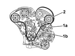
1. Fit the timing belt on the camshaft inlet pulley.
2. Position the roller on the engine and tighten the fixing bolt to the recommended torque.
| Value (daNm) | Components | Fastening | Ø | |
|---|---|---|---|---|
| 8 | FIXED TENSIONER | Bolt |
3. Fit the timing belt on the inlet pulley (3a) and on the exhaust pulley (3b).
1. Fit the timing belt on the moving tensioner (1a), on the water pump pulley (1b) and on the fixed tensioner (1c).
2. Exerting a counter-force through the opening (2a) in the moving tensioner support, fit the bolts (2b) and tighten them to the recommended torque.
| Value (daNm) | Components | Fastening | Ø | |
|---|---|---|---|---|
| 2.5 | MOBILE TIMING TENSIONER | Bolts |
1. Exert a counter-force through the opening (1a) and tension the timing belt (1b) rotating the tensioner roller in an anti-clockwise direction until it is in the end of travel position.
2. Tighten the nut on the timing belt moving tensioner to the recommended torque.
| Value (daNm) | Components | Fastening | Ø | |
|---|---|---|---|---|
| 2 | 1 | MOVING TENSIONER | Bolts |
1. Tighten the bolts (1a), (1b), (1c) and (1d) fixing the camshaft pullies to the recommended torque following the order illustrated in the diagram.
| Value (daNm) | Components | Fastening | Ø | |
|---|---|---|---|---|
| 1a | 1 | DRIVE PULLEY(PULLIES) TIMING | Bolts |
| Value (daNm) | Components | Fastening | Ø | |
|---|---|---|---|---|
| 1b | 1 | DRIVE PULLEY(PULLIES) TIMING | Bolts |
| Value (daNm) | Components | Fastening | Ø | |
|---|---|---|---|---|
| 1c | 1 | DRIVE PULLEY(PULLIES) TIMING | Bolts |
| Value (daNm) | Components | Fastening | Ø | |
|---|---|---|---|---|
| 1d | 1 | DRIVE PULLEY(PULLIES) TIMING | Bolts |
Before completing two revolutions of the crankshaft, make sure that the timing pins slide freely in the housings in the camshaft pullies. If this is not the case, loosen the bolts fixing the camshaft pullies, then position the drive pulley so that the timing pins can be extracted. Tighten to torque taking care to start with the bolt furthest away from the timing pin.
- Remove the timing pulley retaining tools.
| Description | Code | Function | |
|---|---|---|---|
| Pins | 1.870.893.000 | Reaction pins for timing pullies |
- Rotate the crankshaft throught two revolutions in its normal direction of rotation.
Never rotate in the opposite direction to the normal one.
- Position the retaining tool on the crankshaft pulley only.
| Description | Code | Function | |
|---|---|---|---|
| Pins | 1.870.893.000 | Reaction pins for timing pullies |
1. Loosen the nut retaining the timing belt moving tensioner.
2. Align the tensioner roller references (2a) and (2b).
- Tighten the nut on the timing belt moving tensioner loosened previously.
| Value (daNm) | Components | Fastening | Ø | |
|---|---|---|---|---|
| 1 | 2.5 | MOVING TENSIONER | Bolts |
- Remove the retaining tool from the crankshaft pulley.
| Description | Code | Function | |
|---|---|---|---|
| Pins | 1.870.893.000 | Reaction pins for timing pullies |
- Rotate the crankshaft throught two revolutions in its normal direction of rotation.
Never rotate in the opposite direction to the normal one.
- Check the position of the timing belt moving tensioner.
If the references on the timing belt tensioner roller were not aligned, repeat the operation of fitting the belt.
1. Fit the retaining tools (1a) in the special housings in the timing pullies (1b).
| Description | Code | Function | |
|---|---|---|---|
| 1a | Pins | 1.870.893.000 | Reaction pins for timing pullies |
2. Check that the references (2a) for the adjustment of the camshafts engage freely in the heads (2b) until they are in contact with the camshaft pinions.
If this is not the case, start the operation of fitting the belt again.
- Remove the timing pulley retaining tools.
| Description | Code | Function | |
|---|---|---|---|
| Pins | 1.870.893.000 | Reaction pins for timing pullies |
Apply FRENETANCH thread-locking agent, or a similar product, to the auxiliary drive pulley fixing bolts.
- Tighten the bolts fixing the auxiliary drive pulley to the recommended torque.
| Value (daNm) | Components | Fastening | Ø | |
|---|---|---|---|---|
| 2.5 | CRANKSHAFT PULLEY | Bolt | M8 |
- Position the timing or cam angle sensors for the front head and the rear head, then tighten the fixing bolts.
- Position the front head and rear head phase transformer sensors and tighten the fixing bolts.
- Position the intake manifold gaskets on the cylinder heads.
- Position the intake manifold and tighten the fixing nuts.
- Position the fuel manifolds on the front and rear heads, then tighten the fixing bolts.
- Fit the ignition coils for the cylinder heads in their housings.
- Fit the tappet covers on the cylinder heads.
The tappet covers have a composite seal which can be removed and refitted several times. If the gasket is torn, it can be partly repaired using SILICONE CATEGORIE 2 special compound.
1. Tighten the tappet cover fixing bolts, following the procedure described below bearing in mind that the tightening order illustrated in the diagram should be followed for each stage.
- Pre-tighten the tappet cover fixing bolts to the value given in the table.
| Value (daNm) | Components | Fastening | Ø | |
|---|---|---|---|---|
| 0.5 | TAPPET COVERS | Bolt | M |
- Tighten the bolts fixing the tappet covers permanently to the recommended torque.
| Value (daNm) | Components | Fastening | Ø | |
|---|---|---|---|---|
| 0.8 | TAPPET COVERS | Bolt | M |
- Connect the electrical connections for the ignition coils and the electrical connection for the phase transformer actuator.
| Description | Connector | |
|---|---|---|
| Ignition coils | See A030 Ignition coil |
| Description | Connector | |
|---|---|---|
| Phase transformer solenoid valve | See N076 |
| Description | Connector | |
|---|---|---|
| Phase transformer solenoid valve | See N076 PHASE TRANSFORMER ACTUATOR |
- Positionthe electrical connection for the engine cable loom coupling on the tappet cover and tighten the fixing bolt.
- Connect the electrical connections for the cylinder position reference sensors.
| Description | Connector | |
|---|---|---|
| 1 | Cylinder reference sensor | See K168 |
| Description | Connector | |
|---|---|---|
| 2 | Cylinder reference sensor | See K169 CYLINDER REFERENCE SENSOR -2 |
1. Position the gasket (1a) for the intake chamber on the inlet ducts. Tighten the intake chamber (1b) fixing bolts, following the procedure described below bearing in mind that the tightening order illustrated in the diagram should be followed for each stage.
- Pre-tighten the intake chamber fixing bolts to the value given in the table.
| Value (daNm) | Components | Fastening | Ø | |
|---|---|---|---|---|
| 0.4 | INLET AIR DUCT | Bolt | M |
- Tighten the bolts fixing the intake chamber permanently to the recommended torque.
| Value (daNm) | Components | Fastening | Ø | |
|---|---|---|---|---|
| 0.8 | INLET AIR DUCT | Bolt | M |
2. Tighten the nuts (2a) fixing the intake chamber, then connect the oil vapour recovery pipe (2b) to the throttle casing.
Complete with
Parts & tools for this job Staging For 2002 Fiat Ulysse
- TOOLOBD2 scannerSearch: OBD2 scanner
- TOOLDigital multimeterSearch: automotive digital multimeter
- TOOLBack-probe test leadsSearch: back probe test leads
Links open Amazon search results in a new tab. As an Amazon Associate I earn from qualifying purchases.