
Piston connecting rod set - r r
- Make
- Fiat
- Model
- Doblò Factory Service Manual
- Year
- 2000–2010
- Section
- Pistons and connecting rods › Piston connecting rod set - r r
Piston connecting rod set - r r
Removing
Op. 1020A24 CRANKCASE OIL SUMP - R + R CLEAN SEALS FOR SEALANT APPLICATION WITH ENGINE REMOVED
1. Position the flywheel lock.
| Description | Code | |
|---|---|---|
| 1 | Counter-torque | 1.860.846.000 |
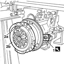
2. Undo the bolts (2a) and remove the clutch plate (2b).
1. Remove the two engine flywheel fixing bolts and position the tool (1a) for rotating the crankshaft.
| Description | Code | |
|---|---|---|
| 1a | Flange | 1.860.815.000 |
Remove the engine flywheel lock fitted previously.
Rotate the crankshaft using the tool fitted previously until cylinders 1 and 4 are at T.D.C.
2. Undo the bolts (2a) and remove the connecting rod caps (2b) complete with half-bearings for cylinders 1 and 4.
3. Remove the 1st and 4th cylinder connecting rod and piston assemblies (3a) complete with connecting rod half-bearings (3b).
Carry out the same operations to remove the pistons and connecting rods for cylinders 2 and 3.
Refitting
Turn the crankshaft using the tool fitted previously.
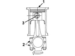
Fit the connecting rod-piston assemblies and align in accordance with the following references.
1. Piston class and arrow indicating camshaft side.
2. Area where the number of the matching cylinder liner is stamped.
3. Gudgeon pin offset.
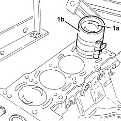
1. Fit the connecting rod-piston assemblies (1a) with half-bearings using tool (1b) to compress the piston rings and then fit the piston into the liner.
| Description | Code | |
|---|---|---|
| 1b | Fitting tool | 1.860.700.000 |
Rotate the engine on the overhaul stand.
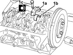
1. Place the connecting rod caps (1a) in their seats complete with half-bearings (1b) and secure them by tightening the bolts (1c) to the recommended torque.
Fit the connecting rod caps so that the number stamped on each cap faces towards the same side as the number stamped on the big end.
| Fastening | Component | dia | Value (daNm) | |
|---|---|---|---|---|
| 1c | Bolt | CONNECTING ROD CAP FASTENERS | M8 | 4.1 |
Remove the tool for rotating the crankshaft.
| Description | Code | |
|---|---|---|
| Flange | 1.860.815.000 |
Fit the flywheel lock.
| Description | Code | |
|---|---|---|
| Counter-torque | 1.860.846.000 |
Fit the two bolts removed previously securing the flywheel and tighten them to the recommended torque.
| Fastening | Component | dia | Value (daNm) | |
|---|---|---|---|---|
| Bolt | FLYWHEEL (MECH.) | M8 X 1.25 | 4.4 |
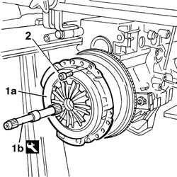
1. Align the driven plate to install clutch assembly (1a), using locating pin (1b).
| Description | Code | |
|---|---|---|
| 1b | Clutch locating tool | 1.870.418.000 |
2. Tighten the bolts fixing the clutch to the engine flywheel.
Remove the flywheel locking tool applied previously.
Op. 1020A24 CRANKCASE OIL SUMP - R + R CLEAN SEALS FOR SEALANT APPLICATION WITH ENGINE REMOVED.
Removing
Op. 1020A24 CRANKCASE OIL SUMP - R + R CLEAN SEALS FOR SEALANT APPLICATION WITH ENGINE REMOVED
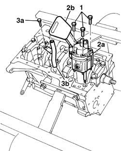
1. Undo the retaining bolts.
2. Remove the engine oil pump (2a) complete with oil suction device (2b).
Keep the oil pump gasket.
3. Undo the fixing bolt (3a) and remove the section inside the crankcase (3b) for the engine oil dipstick.
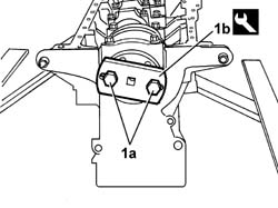
1. Use service bolts (1a) to fit the tool (1b) used to rotate the crankshaft.
| Description | Code | |
|---|---|---|
| 1b | Flange | 1.860.815.000 |
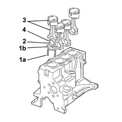
1. Undo the fixing bolts (1a) and remove the connecting rod cap (1b).
2. Remove the lower connecting rod half-bearing.
3. Remove the connecting rod-piston assembly.
4. Remove the upper connecting rod half-bearing.
Refitting
Turn the crankshaft using the tool fitted previously.
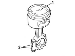
1. The connecting rod-piston assemblies are fitted with the engine rotation arrow (1a) stamped on the piston crown pointing towards the inlet side.
2. Check that the stamp on the cylinder bore/liner to which the connecting rod belongs is on the exhaust side.
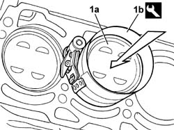
1. Fit the connecting rod-piston assembly (1a) with half-bearing using the tool (1b) to compress the piston rings and then fit the piston into the bore/liner.
| Description | Code | |
|---|---|---|
| Fitting tool | 1.860.700.000 |
Fit the crankpin caps.
Tighten the nuts fixing the connecting rod caps to torque.
| Fastening | Component | dia | Value (daNm) | |
|---|---|---|---|---|
| Nut | CONNECTING ROD CAP FASTENERS | M9 | 5.1 |
Remove the tool for rotating the crankshaft.
| Description | Code | |
|---|---|---|
| Flange | 1.860.815.000 |
Fit the crankcase internal section for the engine oil dipstick.
Position a new oil pump gasket.
Fit the oil pump tightening the fixing bolts to torque.
| Fastening | Component | dia | Value (daNm) | |
|---|---|---|---|---|
| Bolt | ENGINE OIL PUMP | M6 | 2.5 |
Op. 1020A24 CRANKCASE OIL SUMP - R + R CLEAN SEALS FOR SEALANT APPLICATION WITH ENGINE REMOVED
Removing
1. Undo the bolts (1a) and remove the air conditioner compressor (1b).
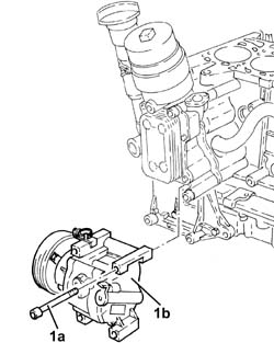
1. Undo the bolts (1a) and remove the air conditioner compressor mount (1b).
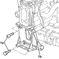
Rotate the engine through 180° on the overhaul stand.
1. Undo the bolts (1a) and remove the connecting rod caps (1b).
2. Remove the lower crankpin half-bearings.
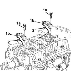
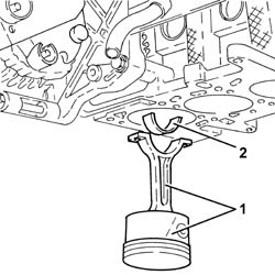
1. Remove the connecting rod - piston assemblies.
2. Remove the upper connecting rod half-bearings.
Refitting
Clean the parts removed thoroughly and check their condition visually.
Lubricate all the mechanical components with engine oil.
Check the connecting rod bearings, noting that the half-bearings should not be adapted. Replace them if scoring or signs of binding are noted.
1. Fit the tool.
| Description | Code | |
|---|---|---|
| 1 | Flange | 1.860.815.000 |
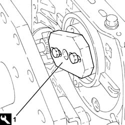
Turn the crankshaft using the tool fitted previously.
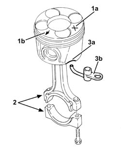
Fit the connecting rod-piston assemblies and align in accordance with the following references.
1. Piston class (1a) and arrow (1b) indicating camshaft side.
2. Area where the number of the matching cylinder liner is stamped.
3. Exhaust (3a) on the piston skirt to be aligned with oil spray (3b).
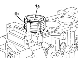
1. Refit the piston-connecting rod assemblies (1a) in their seats with upper connecting rod bearing halves using tool (1b).
The connecting rod bearing halves may be identified as follows:
upper connecting rod bearing half, connecting rod side, trimetallic and dark in colour;
lower connecting rod bearing half, cap side bimetallic, light coloured with a hole.
Never reverse the positioning of the connecting rod bearing halves under any circumstances.
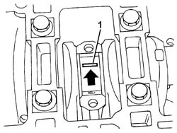
Rotate the engine through 180° on the overhaul stand.
1. Fit the calibrated wire (plastigage) for measuring the bearing clearance.
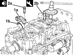
1. Refit the connecting rod cap assemblies (1a) in their seats with upper connecting rod bearing halves using tool (1b).
The connecting rod bearing halves may be identified as follows:
upper connecting rod bearing half, connecting rod side, trimetallic and dark in colour;
lower connecting rod bearing half, cap side bimetallic, light coloured with a hole.
Never reverse the positioning of the connecting rod bearing halves under any circumstances.
2. Tighten the connecting rod cap bolts (2a) to the recommended torque using the angular tightening tool (2b).
| Fastening | Component | dia | Value (daNm) | |
|---|---|---|---|---|
| 2a | Bolt | CONNECTING ROD CAPS | M8 | 1.9 ÷ 2.1 + 40? ± 2? |
| Description | Code | |
|---|---|---|
| 2b | Torque wrench | 1.860.942.000 |
Undo the bolts and remove the connecting rod caps with the half-bearings fitted previously.
1. Use an appropriate graduated measuring tool (1a) to measure the clearance indicated by the plastigage (1b).
Check one journal at a time, without rotating the crankshaft.
| Measurement | Value | ||
|---|---|---|---|
| 1b | Crankshaft crankpins (mm) | 0.030 ÷ 0.062 |
If the figure measured is outside of the tolerance, replace the connecting rod half-bearings with ones of the correct size and category.
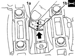
Fit the connecting rod caps permanently by tightening the bolts as shown previously.
Remove the tool.
| Description | Code | |
|---|---|---|
| Flange | 1.860.815.000 |
1. Place the air conditioner compressor mounting (1a) in its housing and secure it tightening the bolts (1b) to the recommended torque.
| Fastening | Component | dia | Value (daNm) | |
|---|---|---|---|---|
| 1b | Bolt | COMPRESSOR MOUNT (AC) | M8 | (Upper and lower engine crankcase side) 2.3 - 2.8 |
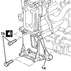
1. Place the air conditioner compressor mounting (1a) in its housing and secure it tightening the bolts (1b) to the recommended torque.
| Fastening | Component | dia | Value (daNm) | |
|---|---|---|---|---|
| 1b | Bolt | AIR CONDITIONER ASSEMBLY COMPRESSOR | M8 | (Mount side) 2.3 - 2.8 |
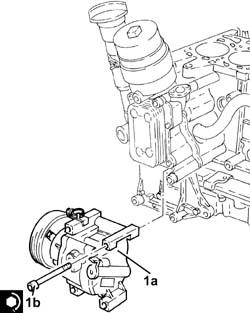
Removing
Op. 1004D40 ENGINE - POSITION ON STAND AND REMOVE
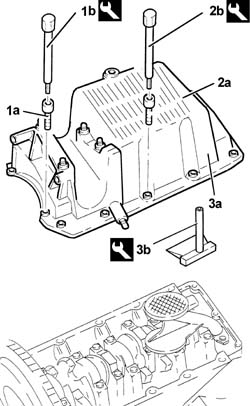
1. Undo the front and rear bolts (1a) fixing the crankcase sump using the tool (1b).
| Description | Code | |
|---|---|---|
| 1b | Spanner | 1.860.833.000 |
2. Undo engine block sump side bolts (2a) using tool (2b), noting that the rubber plugs on the metal casing must be removed to reach the flywheel side bolts.
| Description | Code | |
|---|---|---|
| 2b | Spanner | 1.860.834.000 |
3. Remove the crankcase sump (3a).
To release the sump from the crankcase, tap tool (3b) in between them using a mallet, then use a screwdriver for leverage in the projections in the sides of the crankcase sump.
| Description | Code | |
|---|---|---|
| 3b | Blade | 1.870.718.000 |
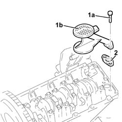
1. Undo the bolts (1a) and remove the engine oil intake duct (1b).
2. Remove the seal.
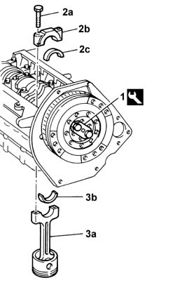
1. Fit the tool and rotate the crankshaft until the cylinder concerned is at B.D.C.
| Description | Code | |
|---|---|---|
| 1 | Flange | 1.860.815.000 |
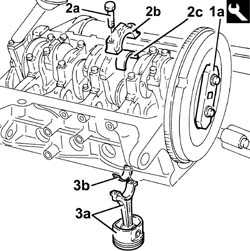
2. Undo the bolts (2a) and remove the connecting rod cap (2b) complete with half-bearing (2c).
Mark the connecting rod caps with a progressive number to define their position for installation.
3. Remove the piston-connecting rod assembly (3a) complete with half-bearing (3b).
Carry out the same operations to remove the pistons and connecting rods for the remaining cylinders.
Refitting
Rotate the crankcase through 90° on the overhaul stand.
Rotate the crankshaft using the tool fitted previously until the cylinder concerned is at B.D.C.
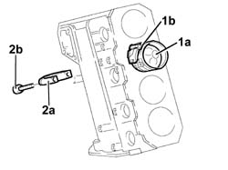
1. Fit the piston-connecting rod assembly (1a) complete with half-bearing using the tool (1b).
Fit the piston-connecting rod assemblies in the crankcase so that the oil spray undercut on the piston is facing the inlet side.
2. Fit the connecting rod cap (2a) complete with half-bearing and secure it without tightening the bolts (2b).
Fit the connecting rods so that the number stamped on each rod faces toward the same side as the number stamped on the big end (inlet side).
Carry out the same operations to refit the pistons and connecting rods for the remaining cylinders.
Rotate the crankcase through 90° on the overhaul stand.
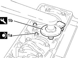
1. Tighten the connecting rod cap bolts (1a) to the recommended torque using the angular tightening tool (1b).
| Fastening | Component | dia | Value (daNm) | |
|---|---|---|---|---|
| 1a | Bolt | CONNECTING ROD CAPS | M9 | 2.5 + 60° |
| Description | Code | |
|---|---|---|
| 1b | Torque wrench | 1.860.942.000 |
Remove the tool.
| Description | Code | |
|---|---|---|
| Flange | 1.860.815.000 |
Fit the engine oil intake complete with gasket and secure it using the bolts.
Apply sealant to the entire perimeter of the crankcase sump.
| Type | Component | Description | Qty. | |
|---|---|---|---|---|
| Silicon sealant | Air conditioning circuit | Silicon sealant |
Fit the crankcase sump.
Tighten the side bolts fixing the crankcase sump to the recommended torque using the tool.
| Fastening | Component | dia | Value (daNm) | |
|---|---|---|---|---|
| Side bolts | ENGINE OIL SUMP | M8 | 2.5 |
| Description | Code | |
|---|---|---|
| 1 | Spanner | 1.860.834.000 |
Tighten the front and rear bolts fixing the crankcase sump to the recommended torque using the tool.
| Fastening | Component | dia | Value (daNm) | |
|---|---|---|---|---|
| Front and rear bolts | ENGINE OIL SUMP | M6 | 0.9 |
| Description | Code | |
|---|---|---|
| 1 | Spanner | 1.860.833.000 |
Op. 1004D40 ENGINE - POSITION ON STAND AND REMOVE
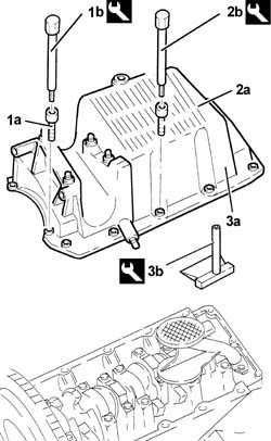
Removing
1. Undo the front and rear bolts (1a) fixing the crankcase sump using the tool (1b).
| Description | Code | |
|---|---|---|
| 1b | Spanner | 1.860.833.000 |
2. Undo the side bolts (2a) fixing the crankcase sump using the tool (2b).
| Description | Code | |
|---|---|---|
| 2b | Spanner | 1.860.834.000 |
3. Remove the crankcase sump (3a).
To release the sump from the crankcase, tap tool (3b) in between them using a mallet, then use a screwdriver for leverage in the projections in the sides of the crankcase sump.
| Description | Code | |
|---|---|---|
| 3b | Blade | 1.870.718.000 |
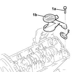
1. Undo the bolts (1a) and remove the engine oil intake duct (1b).
2. Remove the seal.
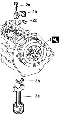
1. Fit the tool and rotate the crankshaft until the cylinder concerned is at B.D.C.
| Description | Code | |
|---|---|---|
| 1 | Flange | 1.860.815.000 |
2. Undo the bolts (2a) and remove the connecting rod cap (2b) complete with half-bearing (2c).
Mark the connecting rod caps with a progressive number to define their position for installation.
3. Remove the piston-connecting rod assembly (3a) complete with half-bearing (3b).
Carry out the same operations to remove the pistons and connecting rods for the remaining cylinders.
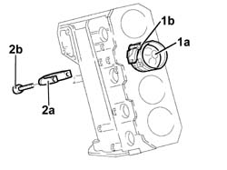
Refitting
Rotate the crankcase through 90° on the overhaul stand.
Rotate the crankshaft using the tool fitted previously until the cylinder concerned is at B.D.C.
1. Fit the piston-connecting rod assembly (1a) complete with half-bearing using the tool (1b).
Fit the piston-connecting rod assemblies in the crankcase so that the oil spray undercut on the piston is facing the inlet side.
2. Fit the connecting rod cap (2a) complete with half-bearing and secure it without tightening the bolts (2b).
Fit the connecting rods so that the number stamped on each rod faces toward the same side as the number stamped on the big end (inlet side).
Carry out the same operations to refit the pistons and connecting rods for the remaining cylinders.
Rotate the crankcase through 90° on the overhaul stand.
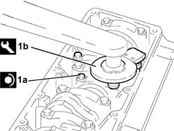
1. Tighten the connecting rod cap bolts (1a) to the recommended torque using the angular tightening tool (1b).
| Fastening | Component | dia | Value (daNm) | |
|---|---|---|---|---|
| 1a | Bolt | CONNECTING ROD CAPS | M9 | 2.4 - 2.6 + 60° |
| Description | Code | |
|---|---|---|
| 1b | Torque wrench | 1.860.942.000 |
Remove the tool.
| Description | Code | |
|---|---|---|
| Flange | 1.860.815.000 |
Fit the engine oil intake complete with gasket and secure it using the bolts.
Apply sealant to the entire perimeter of the crankcase sump.
| Type | Component | Description | Qty. | |
|---|---|---|---|---|
| Sealant | ENGINE OIL SUMP | Silicon sealant |
Fit the crankcase sump.
Tighten the side bolts fixing the crankcase sump to the recommended torque using the tool.
| Fastening | Component | dia | Value (daNm) | |
|---|---|---|---|---|
| Side bolts | ENGINE OIL SUMP | M8 | 2.1 - 2.6 |
| Description | Code | |
|---|---|---|
| Spanner | 1.860.834.000 |
Tighten the front and rear bolts fixing the crankcase sump to the recommended torque using the tool.
| Fastening | Component | dia | Value (daNm) | |
|---|---|---|---|---|
| Front and rear bolts | ENGINE OIL SUMP | M6 | 0.7 - 0.9 |
| Description | Code | |
|---|---|---|
| Spanner | 1.860.833.000 |
Tighten the bolt connecting the crankcase sump to the intermediate shaft support.
Refer to
Parts & tools for this job Staging For 2000 Fiat Doblò
- PARTEngine gasket setSearch: Fiat Doblò 2000 engine gasket set
- TOOLTorque wrenchSearch: 3/8 inch torque wrench
- TOOLFeeler gauge setSearch: feeler gauge set
Links open Amazon search results in a new tab. As an Amazon Associate I earn from qualifying purchases.