
Water pump - r + r with engine removed
- Make
- Alfa Romeo
- Model
- GT Factory Service Manual
- Year
- 2003–2010
- Section
- Engine cooling › Water pump - r + r with engine removed
WATER PUMP - R + R WITH ENGINE REMOVED
Removing
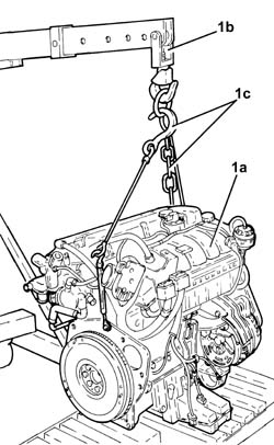
1. Secure and support the engine (1a) using a hydraulic lift (1b) fitted with suitable chains (1c).
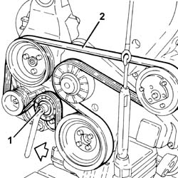
1. Adjust the mobile tensioner to slacken the auxiliary drivebelt.
2. Release and remove the auxiliary drivebelt.
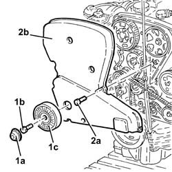
1. Remove plug (1a), unscrew bolt (1b) and remove the fixed auxiliary drivebelt tensioner (1c).
2. Undo the fixing bolts (2a) and remove the upper protective timing cover (2b).
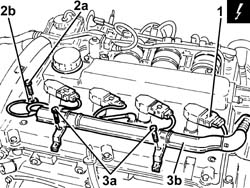
1. Disconnect the electrical connections from the ignition coils.
| Description | Connector | |
|---|---|---|
| 1 | Ignition coil | See A30 IGNITION ''COIL |
2. Undo the bolt (2a) and disconnect the earth lead (2b) from the cam cover.
3. Undo the bolts (3a) and move bulkhead coupling (3b) aside.
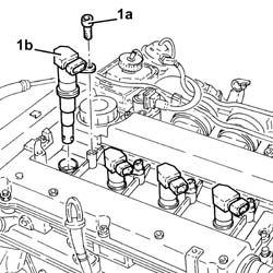
1. Undo the bolts (1a) and remove the ignition coils (1b).
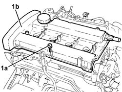
1. Undo the bolts (1a) and remove the cam cover (1b) complete with gasket.
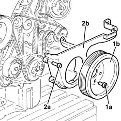
1. Undo the bolts (1a) and remove the crankshaft pulley (1b).
2. Undo the fixing bolts (2a) and remove the lower protective timing cover (2b).
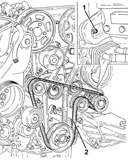
1. Loosen the counter-rotating shaft toothed drive belt tensioner nut.
2. Release and remove the toothed timing drive belt.
1. Unscrew bolts (1a) and remove the counterrotating shaft toothed drive belt drive pulley (1b).
2. Loosen the nut retaining the timing belt mobile tensioner.
3. Release and remove the toothed timing drive belt.
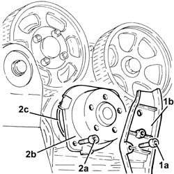
1. Undo the fixing bolts (1a) and remove the side protective timing cover (1b).
2. Undo the bolts (2a) and remove the water pump (2b) complete with O-ring (2c).
Refitting
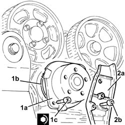
1. Position the water pump (1a), complete with O-ring (1b), in its housing and secure it tightening the bolts (1c) to the recommended torque.
| Fastening | Component | Ø | Value (daNm) | |
|---|---|---|---|---|
| 1c | Bolt | COOLANT PUMP | M8 | (Cylinder head side) 2.3 - 2.8 |
2. Fit the side cover (2a) protecting the timing belt and secure it using the bolt (2b).
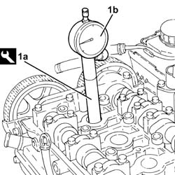
1. Fit the tool (1a) complete with dial gauge (1b) in the seat for the spark plug for cylinder no. 1.
| Description | Code | |
|---|---|---|
| 1a | Extension | 1.860.895.001 |
Rotate the crankshaft until the piston for cylinder no. 1 is at T.D.C. on the combustion stroke.
If TDC is exceeded, do not turn backwards but proceed with the rotation in the same direction rotating the crankshaft through another two revolutions and return the piston for cylinder no. 1 to TDC.
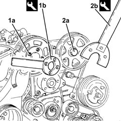
1. Undo the inlet side driven timing pulley bolt (1a) using the tool (1b) for counter-torque.
| Description | Code | |
|---|---|---|
| 1b | Counter-torque | 1.860.856.001 |
2. Undo the exhaust side driven timing pulley bolt (2a) using the tool (2b) for counter-torque.
| Description | Code | |
|---|---|---|
| 2b | Spanner for rotating timing pullies | 1.860.831.002 |
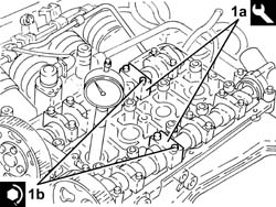
Undo the bolts and remove the inlet side camshaft fourth cap and the exhaust side camshaft second cap.
1. Fit the tool (1a) in place of the camshaft caps that have been removed and secure them tightening the bolts (1b) to the recommended torque.
Check that the camshaft cam profile and the tool are correctly aligned.
| Description | Code | |
|---|---|---|
| 1a | Templates | 1.870.859.000 |
| Fastening | Component | Ø | Value (daNm) | |
|---|---|---|---|---|
| 1b | Bolt | TEMPLATES FOR ENGINE TIMING | M7 | (Cylinder head side) 1.0 |
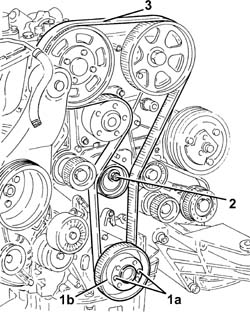
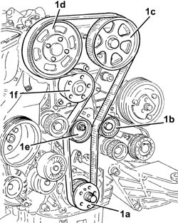
1. Fit the timing toothed drive belt in the following order:
toothed drive pulley (1a)
fixed tensioner (1b)
exhaust side toothed driven pulley (1c)
Before fitting the belt on the exhaust side toothed driven pulley, turn clockwise (see figure) to the end of its travel.
inlet side toothed driven pulley (1d)
Before fitting the belt on the intake side toothed driven pulley, turn clockwise (see figure) to the end of its travel.
moving tensioner (1e)
water pump pulley (1f).
The belt is fitted with the arrow facing the direction of rotation of the engine (clockwise - timing end).
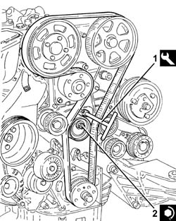
1. Use the tool to rotate the moving timing tensioner until the timing belt is completely taut.
| Description | Code | |
|---|---|---|
| 1 | Spanner | 1.822.149.000 |
2. Tighten the nut fixing the moving timing tensioner to the recommended torque.
| Fastening | Component | Ø | Value (daNm) | |
|---|---|---|---|---|
| 2 | Nut | MOBILE TIMING TENSIONER | M8 | 2.3 ÷ 2.8 |
1. Tighten the bolts (1a) for the inlet side toothed timing driven pulley using tool (1b) for counter-torque.
| Fastening | Component | Ø | Value (daNm) | |
|---|---|---|---|---|
| 1a | Bolt | TIMING DRIVEN PULLIES | M6 | (Inlet camshaft side) 0.8 - 1.0 |
| Description | Code | |
|---|---|---|
| 1b | Counter-torque | 1.860.856.001 |
2. Tighten the exhaust side driven timing pulley bolt (2a) to the specified torque using the tool (2b) for counter-torque.
| Fastening | Component | Ø | Value (daNm) | |
|---|---|---|---|---|
| 2a | Bolt | TIMING DRIVEN PULLIES | M12 | (Exhaust camshaft side) 10.8-13.2 |
| Description | Code | |
|---|---|---|
| 2b | Spanner for rotating timing pullies | 1.860.831.002 |
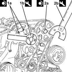
Remove the camshaft timing tools.
| Description | Code | |
|---|---|---|
| Templates | 1.870.859.000 |
Place the camshaft caps previously removed in their housings and secure them tightening the bolts to the recommended torque.
| Fastening | Component | Ø | Value (daNm) | |
|---|---|---|---|---|
| Bolt | CAMSHAFT SUPPORTS | M7 | (Cylinder head side) 1.4 - 1.7 |
Turn the crankshaft through two turns in the direction of rotation (clockwise - timing end) and move the cylinder 1 piston to TDC.
1. Insert tool (1a) to hold the mobile timing belt tensioner still and loosen tensioner nut (1b).
| Description | Code | |
|---|---|---|
| 1a | Spanner | 1.822.149.000 |
2. Turn tool (2a) anticlockwise (timing end) to align the tensioner mobile pointer (2b) with reference hole (2c).
| Description | Code | |
|---|---|---|
| 2a | Spanner | 1.822.149.000 |
3. Tighten the nut fixing the moving timing tensioner to the recommended torque.
| Fastening | Component | Ø | Value (daNm) | |
|---|---|---|---|---|
| 3 | Nut | MOBILE TIMING TENSIONER | M8 | 2.3 ÷ 2.8 |
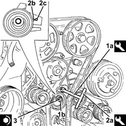
Turn the crankshaft through two turns in the direction of rotation (clockwise - timing end) to move cylinder 1 to TDC in combustion stage and check that the engine timing is correct using the tool.
| Description | Code | |
|---|---|---|
| Templates | 1.870.859.000 |
Remove the tool for checking T.D.C. from the housing for the spark plug for cylinder no.1.
| Description | Code | |
|---|---|---|
| Extension | 1.860.895.001 |
Place the spark plug for cylinder no.1 in its housing and tighten it to the recommended torque.
| Fastening | Component | Ø | Value (daNm) | |
|---|---|---|---|---|
| SPARK PLUGS | M14 | (Cylinder head side) 2.4 - 3.0 |
- Position the crankshaft pulley in its housing and secure it tightening the bolts to the recommended torque.
| Fastening | Component | Ø | Value (daNm) | |
|---|---|---|---|---|
| Bolt | COUNTER-ROTATING SHAFT DRIVE PULLEY | M6 | (Timing belt drive pulley side) 0.8÷1.0 |
1. Turn the counterrotating shafts until the notches (1a) on the pulleys are aligned with the ribs (1b).
2. Fit the lower protective timing cover and the crankshaft pulley provisionally and check the alignment of the notches stamped on the parts.
Fit the counterrotating shaft toothed drive belt
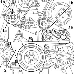
1. Tension the counterrotating shaft toothed drivebelt using tool (1a) to move alignment hole (1b) on the tensioner to the middle of the rotation sector.
| Description | Code | |
|---|---|---|
| 1a | Spanner | 1.822.154.000 |
2. Tighten the nut fixing the toothed timing belt tensioner to the recommended torque.
| Fastening | Component | Ø | Value (daNm) | |
|---|---|---|---|---|
| 2 | Nut | BELT TENSIONER COUNTER-ROTATING SHAFT | M6 | (Left counter-rot shaft cover side) 0.8 - 1.0 |
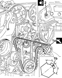
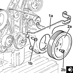
1. Fit the lower timing belt covers (1a) and secure them using the bolts (1b).
2. Position the crankshaft pulley (2a) in its housing and secure it tightening the bolts (2b) to the recommended torque.
| Fastening | Component | Ø | Value (daNm) | |
|---|---|---|---|---|
| 2b | Bolt | CRANKSHAFT PULLEY | M8 | 2.3 ÷ 2.8 |
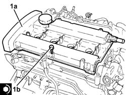
1. Place the cam cover (1a), complete with gasket, back in its housing and secure it tightening the bolts (1b) to the recommended torque.
| Fastening | Component | Ø | Value (daNm) | |
|---|---|---|---|---|
| 1b | Bolt | CAM COVER | M6 | (Cylinder head side) 0.8 - 1.0 |
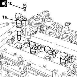
1. Replace the ignition coils (1a) in their housings with gaskets and secure them tightening the bolts (1b) to the recommended torque.
| Fastening | Component | Ø | Value (daNm) | |
|---|---|---|---|---|
| 1b | Bolt | IGNITION COIL/REEL | M6 | (Cam cover side) 0.8 ÷ 1.0 |
Fit the bulkhead coupling in its housing and secure it using the bolts.
Connect the battery earth lead to the cam cover and secure it using the bolt.
Connect the electrical connections to the ignition coils.
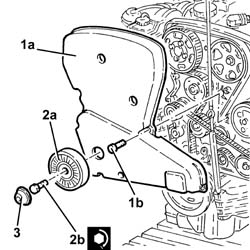
1. Fit the lupper timing belt covers (1a) and secure them using the bolts (1b).
2. Position the auxiliary drivebelt fixed tensioner (2a) in its housing and secure it tightening the bolt (2b) to the recommended torque.
| Fastening | Component | Ø | Value (daNm) | |
|---|---|---|---|---|
| 2b | Bolt | SINGLE BELT FIXED TENSIONER VARIOUS | M8 | 2.2 ÷ 2.8 |
3. Refit the plug on the auxiliary drivebelt fixed tensioner
Adjust the mobile tensioner and fit the auxiliary drivebelt.
Release the engine from the hydraulic lift.
Removing
Proceed with the removal
Op. 1004D40 ENGINE - POSITION ON STAND AND REMOVE.
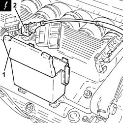
1. Open the electrical connection holder case.
2. Disconnect the electrical connection for the timing side knock sensor.
| Description | Connector | |
|---|---|---|
| 2 | Detonation sensor -1 | See K50 DETONATION SENSOR 1 ( CONNECTORS ) |
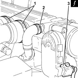
1. Loosen the bands securing the intake manifolds to the air chamber.
2. Loosen the band securing the engine idle oil vapour recovery pipe, air capacity chamber side.
3. Disconnect the electrical connection from the throttle casing with D.V.L.
| Description | Connector | |
|---|---|---|
| 3 | Throttle body actuator | See N75 THROTTLE BODY ACTUATOR ( CONNECTORS ) |
1. Unscrew retaining bolt (1a) and disconnect earth lead (1b) from the air capacity chamber.
| Description | Connector | |
|---|---|---|
| 1b | Earth on engine | See C40 ENGINE EARTH |
2. Unscrew the bolt securing the stiffening rod to the reaction link mount on the engine.
3. Undo bolts (3a) and remove air capacity chamber (3b).
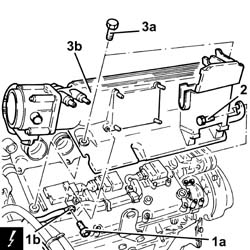
1. Disconnect the electrical connections from the right cylinder head injectors.
| Description | Connector | |
|---|---|---|
| 1 | Injector | See N70 INJECTOR |
2. Disconnect the electrical connections from the right cylinder head ignition coils.
| Description | Connector | |
|---|---|---|
| 2 | Ignition coil | See A30 IGNITION ''COIL |
3. Undo bolts (3a) and move electrical wiring duct (3b) aside.
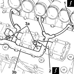
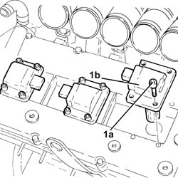
1. Undo the bolts (1a) and remove the ignition coils (1b) from the right cylinder head.
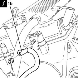
1. Undo the nut (1a) and disconnect the earth lead (1b) from the left cylinder head.
| Description | Connector | |
|---|---|---|
| 1b | Earth on engine | See C40 ENGINE EARTH |
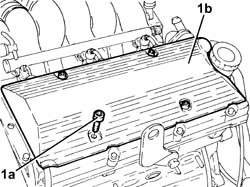
1. Undo the bolts (1a) and remove the ignition coil cover on the left cylinder head (1b).
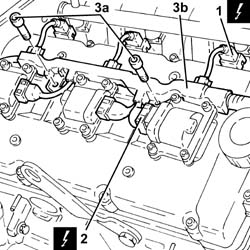
1. Disconnect the electrical connections from the left cylinder head injectors.
| Description | Connector | |
|---|---|---|
| 1 | Injector | See N70 INJECTOR |
2. Disconnect the electrical connections from the left cylinder head ignition coils.
| Description | Connector | |
|---|---|---|
| 2 | Ignition coil | See A30 IGNITION ''COIL |
3. Undo bolts (3a) and move electrical wiring duct (3b) aside.
1. Undo the bolts (1a) and remove the ignition coils (1b) from the left cylinder head.
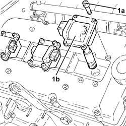
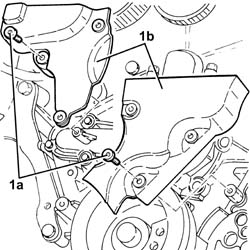
1. Undo the fixing bolts (1a) and remove the upper protective timing cover (1b).
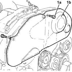
1. Undo the fixing bolts (1a) and remove the lower protective timing cover (1b).
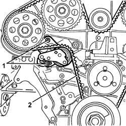
1. Loosen the bolts retaining the timing belt moving tensioner.
2. Prise off the timing drive belt from the toothed driven pullies.
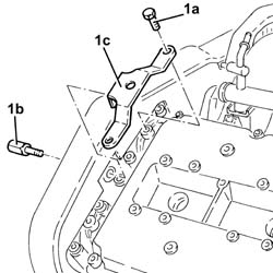
1. Undo the bolts (1a) and bolt (1b) remove bracket (1c).
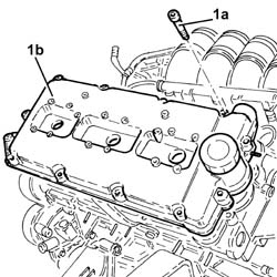
1. Undo the bolts (1a) and remove the left cylinder head cam cover (1b) complete with gasket.
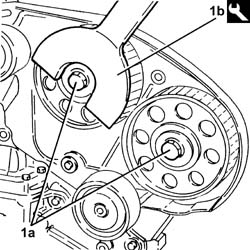
1. Loosen the bolts (1a) for the toothed driven pullies, using the tool (1b) for counter-torque.
| Description | Code | |
|---|---|---|
| 1b | Counter-torque | 1.822.146.000 |
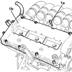
1. Undo the bolts (1a) and remove the right cylinder head cam cover (1b) complete with gasket.
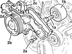
1. Undo the bolt (1a) and remove the fixed timing tensioner (1b).
2. Undo the fixing bolts (2a) and remove the water pump (2b) complete with cover (2c) and bracket (2d).
Take care when removing the water pump not to release the rigid water pump inlet pipe from the thermostat.
3. Remove the seal.
Refitting
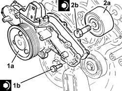
1. Place the water pump (1a), complete with cover, bracket and gasket in position, then tighten the bolts (1b) to the recommended torque.
| Fastening | Component | Ø | Value (daNm) | |
|---|---|---|---|---|
| 1b | Bolt | COOLANT PUMP | M6 | (Engine crankcase side) 0.8 - 1.0 |
2. Position the fixed timing tensioner (2a) in its housing and secure it tightening the bolt (2b) to the recommended torque.
| Fastening | Component | Ø | Value (daNm) | |
|---|---|---|---|---|
| 2b | Bolt | FIXED TENSIONER | M10 | (Cylinder head side) 4.5 - 5.5 |
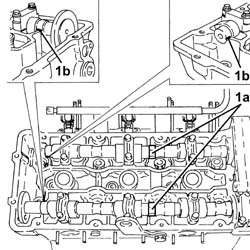
1. Carry out the initial timing of the camshafts. apply a wrench into seat (1a) in the centre of the camshafts and turn to align reference marks (b) on the shafts with the upper cylinder head surface.
The reference marks must face the middle of each cylinder head.
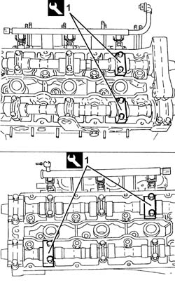
1. Remove caps 4 to 7 from the left cylinder head.
2. Remove caps B and G from the right cylinder head.
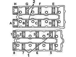
1. Repalce the removed camshaft caps with the timing templates.
| Description | Code | |
|---|---|---|
| 1 | Templates | 1.870.849.000 |
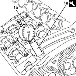
1. Fit the tool (1a) complete with dial gauge (1b) in the seat for the spark plug for cylinder no. 1.
| Description | Code | |
|---|---|---|
| 1a | Fitting tool | 1.821.225.000 |
Rotate the crankshaft through small rotations (in both directions) until the piston for the right head timing side cylinder no. 1 is at T.D.C. in the combustion stroke.
Take care that the last rotation of the crankshaft is in the direction of operation.
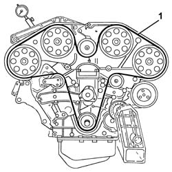
1. Fit the timing drive belt starting from the drive pulley and continuing in an anti-clockwise direction making sure that the drive branches are properly taut.
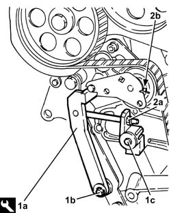
1. Fit the tool (1a) and secure it using bolt (1b) for the alternator bracket and bolt (1c) for the water pump.
The tooth for the tool should engage with the moving part of the mobile timing belt tensioner.
| Description | Code | |
|---|---|---|
| 1a | Belt tensioner | 1.860.950.000 |
2. Act on the belt tensioner tool nut (2a) until the moving reference on the belt tensioner (2b) is under the fixed reference.
1. Tighten bolts (1a) for the right head toothed driven pullies to the specified torque using the tool (1b) for counter-torque.
| Fastening | Component | Ø | Value (daNm) | |
|---|---|---|---|---|
| 1a | Bolt | TIMING DRIVEN PULLIES | M12 | (camshaft side) 7.2 - 8.8 |
| Description | Code | |
|---|---|---|
| 1b | Support for counter-torque | 1.860.831.000 |
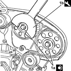
Remove the tools for timing the camshafts.
| Description | Code | |
|---|---|---|
| Templates | 1.870.849.000 |
Place the camshaft caps in their housings to replace the removed tools and secure them tightening the bolts to the recommended torque.
| Fastening | Component | Ø | Value (daNm) | |
|---|---|---|---|---|
| Bolt | CAMSHAFT CAPS | M8 | (Cylinder head side) 1.8 - 2.0 |
Rotate the crankshaft through two revolutions in its direction of rotation to allow the toothed timing belt to bed in.
1. Check that the moving reference for the timing belt tensioner coincides with the fixed reference.
2. If the references are not aligned, gently release the tensioner tension acting on the nut for the tensioning tool until the reference coincide.
3. Tighten the nut fixing the moving timing tensioner to the recommended torque.
| Fastening | Component | Ø | Value (daNm) | |
|---|---|---|---|---|
| 3 | Bolt | MOBILE TIMING TENSIONER | M8 | (Cylinder head side) 1.9 - 2.3 |
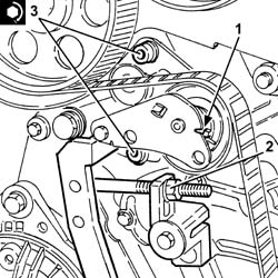
Remove the belt tensioner tool.
| Description | Code | |
|---|---|---|
| Belt tensioner | 1.860.950.000 |
1. - Place the cylinder head cam covers (1a) in their housings with gaskets and secure them tightening the bolts (1b) to the recommended torque.
| Fastening | Component | Ø | Value (daNm) | |
|---|---|---|---|---|
| 1b | Bolt | TAPPET COVERS | M7 | (Cylinder head side) 1.4 - 1.7 |
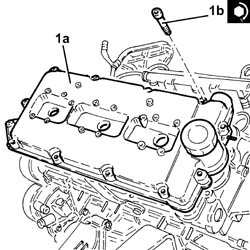
Fit the bracket in its housing and secure it using the bolts.
Fit the lower timing belt covers and secure them using the bolts.
Fit the upper timing belt covers and secure them using the bolts.
1. Replace the left cylinder head ignition coils (1a) in their housings with gaskets and secure them tightening the bolts (1b) to the recommended torque.
| Fastening | Component | Ø | Value (daNm) | |
|---|---|---|---|---|
| 1b | Bolt | IGNITION COIL/REEL | M6 | (Cam cover side) 0.8 ÷ 1.0 |
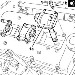
Refit the electrical wiring conduit and secure with bolts.
Connect the electrical connections to the left cylinder head ignition coils.
Connect the electrical connections to the left cylinder head injectors.
Place the ignition coil cover on the left cylinder head back in its housing and secure it using the bolts.
Connect the earth lead to the left cylinder head and secure it using the nut.
1. Replace the right cylinder head ignition coils (1a) in their housings with gaskets and secure them tightening the bolts (1b) to the recommended torque.
| Fastening | Component | Ø | Value (daNm) | |
|---|---|---|---|---|
| 1b | Bolt | IGNITION COIL/REEL | M6 | (Cam cover side) 0.8 ÷ 1.0 |
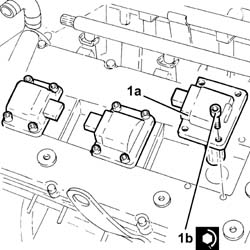
Refit the electrical wiring conduit and secure with bolts.
Connect the electrical connections to the right cylinder head ignition coils.
Connect the electrical connections to the right cylinder head injectors.
Fit the air capacity chamber and secure it using the bolts.
Tighten the bolt securing the stiffening rod to the reaction link mount on the engine.
Connect the earth lead to the air capacity chamber and secure with the bolt.
Connect the electrical connection to the throttle casing with D.V.L.
Tighten the band securing the engine idle oil vapour recovery pipe, air capacity chamber side.
Tighten the bands securing the intake manifolds to the air chamber.
Connect the electrical connection for the timing side knock sensor.
Close the electrical connection holder casing.
Proceed with the refitting
Op. 1004D40 ENGINE - POSITION ON STAND AND REMOVE.
Removing
Proceed with the removal
Op. 1032B16 TOOTHED TIMING BELT - R R WITH ENGINE REMOVED.
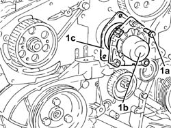
1. Undo the bolts (1a) and remove the coolant pump (1b) complete with gasket (1c).
Refitting
Refit the water pump, complete with gasket, in its housing and secure it tightening the bolts to the recommended torque.
| Fastening | Component | Ø | Value (daNm) |
|---|
Proceed with the refitting
Op. 1032B16 TOOTHED TIMING BELT - R R WITH ENGINE REMOVED.
Removing
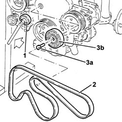
1. Adjust the automatic belt tensioner using the wrench to slacken the auxiliary drivebelt.
2. Remove the single engine components drive belt.
3. Undo the bolt (3a) and remove the engine components single belt cam belt tensioner (3b).
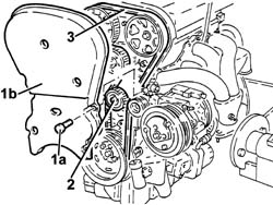
1. Undo the bolts (1a) and remove the timing belt guard (1b).
2. Loosen the timing belt tensioner nut.
3. Release the timing drive belt from the camshaft drive pullies.
1. Undo the bolts (1a) and remove the left side timing belt guard (1b).
2. Loosen the bolts (2a) for the inlet side camshaft pulley using tool (2a) for counter-torque.
| Description | Code | |
|---|---|---|
| 2b | Counter-torque | 1.822.155.000 |
3. Remove the inlet side timing driven pulley.
4. Undo the bolts (4a) and remove the water pump (4b) complete with O-ring (4c).
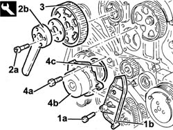
Refitting
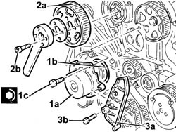
1. Fit the water pump (1a), complete with a new O-Ring (1b) and tighten the bolts (1c) to the recommended torque.
| Fastening | Component | Ø | Value (daNm) | |
|---|---|---|---|---|
| 1c | Bolt | TEMPLATES FOR ENGINE TIMING | M7 | (Cylinder head side) 1.0 |
2. Position the inlet side timing driven pulley (2a) and secure it with bolts (2b) without tightening them.
3. Fit the camsahft side protection (3a) and secure with the bolt (3b).
Loosen the exhaust side camshaft pulley bolt using the tools for countertorque.
| Description | Code | |
|---|---|---|
| Counter-torque | 1.822.146.000 |
| Description | Code | |
|---|---|---|
| Counter-torque | 1.822.156.000 |
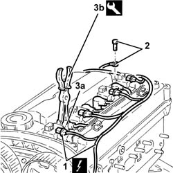
1. Disconnect the electrical connections from the ignition coils.
| Description | Connector | |
|---|---|---|
| 1 | Ignition coil | A30 |
2. Disconnect the earth lead from the cylinder head.
3. Disconnect the high tension leads (3a) from the spark plugs using tool (3b).
| Description | Code | |
|---|---|---|
| 3b | Caliper | 1.820.636.000 |
Unscrew the bolts and remove the bracket with ignition coils and high tension cables.
Undo the bolts and remove the tappet cover complete with gasket.
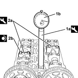
1. Fit the tool (1a) complete with dial gauge (1b) in the seat for the spark plug for cylinder no. 1.
| Description | Code | |
|---|---|---|
| 1a | Extension | 1.825.013.000 |
Rotate the crankshaft until the piston for cylinder no. 1 is at T.D.C. on the combustion stroke.
Unscrew the bolts and remove the third cap on the intake and exhaust side camshafts.
2. Fit tool (2a) in place of the camshaft caps that have been removed and secure them tightening the bolts (2b) to the recommended torque.
Check that the camshaft cam profile and the tool are correctly alignematched.
| Description | Code | |
|---|---|---|
| 2a | Templates | 1.870.734.000 |
| Fastening | Component | Ø | Value (daNm) | |
|---|---|---|---|---|
| 2b | Bolt | TEMPLATES FOR ENGINE TIMING | M7 | (Cylinder head side) 1.0 |
Fit the timing belt.
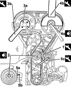
1. Apply maximum tension to the timing belt using the tool.
| Description | Code | |
|---|---|---|
| 1 | Spanner | 1.822.149.000 |
2. Tighten the belt tensioner nut to the recommended torque.
| Fastening | Component | Ø | Value (daNm) | |
|---|---|---|---|---|
| 2 |
3. Loosen the bolts (3a) for the inlet side camshaft pulley using tool (2a) for counter-torque.
| Description | Code | |
|---|---|---|
| 3b | Counter-torque | 1.822.155.000 |
4. Tighten the bolt (4a) for the exhaust side toothed timing driven pulley using the tools (4b) for counter-torque.
| Fastening | Component | Ø | Value (daNm) | |
|---|---|---|---|---|
| 4a |
| Description | Code | |
|---|---|---|
| 4b | Counter-torque | 1.822.156.000 |
| Description | Code | |
|---|---|---|
| 4b | Counter-torque | 1.822.146.000 |
Undo the bolts and remove the tool.
| Description | Code | |
|---|---|---|
| Templates | 1.870.734.000 |
Fit the camshaft cams removed previously and tighten the bolts to the recommended torque.
| Fastening | Component | Ø | Value (daNm) |
|---|
Turn the crankshaft through two turns.
Loosen the timing belt tensioner nut.
5. Align the mobile pointer (5a) on the timing belt tensioner with the reference hole (5b) using tool (5c).
| Description | Code | |
|---|---|---|
| 5c | Spanner | 1.822.149.000 |
Tighten the belt tensioner nut to the recommended torque.
| Fastening | Component | Ø | Value (daNm) |
|---|
Remove the tool complete with dial gauge.
| Description | Code | |
|---|---|---|
| Extension | 1.825.013.000 |
Remove the spark plug for cylinder no. 1.
Fit the cam cover complete with gasket and secure it using the bolts.
Fit the bracket complete with ignition coils and high tension leads and secure with bolts.
Connect the spark plug high tension leads.
Connect the earth lead to the cylinder head.
Connect the electrical connections to the ignition coils.
Fit the upper timing belt guard and secure it using the bolt.
Fit the single components belt fixed tensioner and secure it with the bolt.
Fit the auxiliary drivebelt by using a wrench as a lever on the automatic belt tensioner.
Parts & tools for this job Staging For 2003 Alfa Romeo GT
- PARTEngine gasket setSearch: Alfa Romeo GT 2003 engine gasket set
- TOOLTorque wrenchSearch: 3/8 inch torque wrench
- TOOLFeeler gauge setSearch: feeler gauge set
Links open Amazon search results in a new tab. As an Amazon Associate I earn from qualifying purchases.