
Engine - position on stand and remove
- Make
- Alfa Romeo
- Model
- GT Factory Service Manual
- Year
- 2003–2010
- Section
- Engine and power unit › Engine - position on stand and remove
ENGINE - POSITION ON STAND AND REMOVE
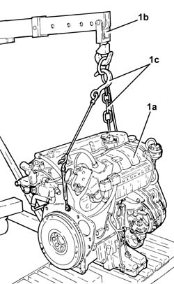
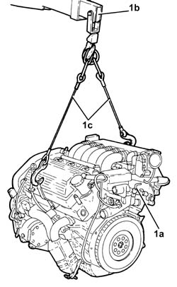
1. Secure and support the engine (1a) using a hydraulic hoist (1b) fitted with suitable chains (1c).
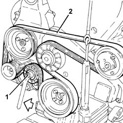
1. Adjust the moving tensioner to loosen the engine components single drive belt tension.
2. Remove the engine components single drive belt.
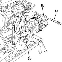
1. Undo the bolts (1a) and remove the air conditioning compressor (1b).
2. Undo the bolts (2a) and remove the air conditioner compressor mounting (2b).
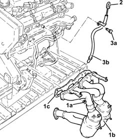
1. Undo the nuts (1a) and remove catalytic converter (1b) complete with gasket (1c).
2. Release and rmove the engine oil dipstick.
3. Undo the nut (3a) and remove the engine oil dipstick pipe (3b).
1. Remove the air conditioner compressor mounting bracket locating bush.
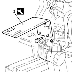
2. Fit the left bracket for supporting the engine on the service stand.
| Name | Country | |
|---|---|---|
| 2 | Brackets | 1.861.001.141 |
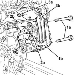
1. Undo the bolts (1a) and remove the alternator (1b).
2. Undo bolts (2a) and remove the rear alternator support bracket (2b).
3. Undo the bolt (3a) and remove the alternator protection (3b).
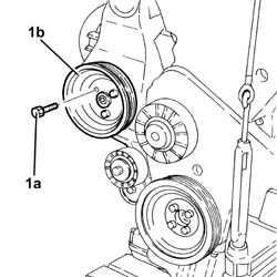
1. Undo the bolts (1a) and remove the power steering pump pulley (1b).
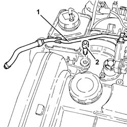
1. Release the coolant return pipe to the coolant reservoir from the attachments from its fastenings.
2. Undo the upper bolt securing the power steering fluid reservoir.
1. Undo the remaining bolt securing the power assisted steering fluid reservoir.
2. Loosen the band and disconnect the supply pipe from the fluid reservoir to the power assisted steering pump, power assisted steering pump side.
3. Remove the power assisted steering fluid reservoir (3a), complete with pipe (3b).
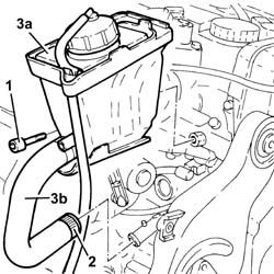
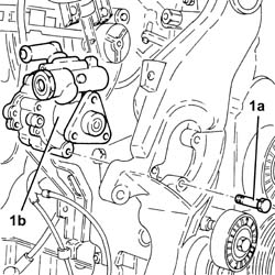
1. Undo the bolts (1a) and remove the power assisted steering pump (1b).
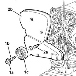
1. Remove the cap (1a), undo the bolt (1b) and remove the single belt fixed tensioner (1c).
2. Undo the bolts (2a) and remove the upper protective timing cover (2b).
1. Undo the bolts (1a) and remove the bracket (1b) after releasing it from the electrical wiring.
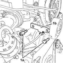
1. Undo the bolts (1a) and remove the modular intake manifold mounting bracket (1b) after having released it from the electrical wiring.
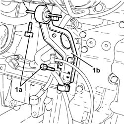
1. Undo the bolt securing the intermediate drive shaft mounting to the crankcase oil sump.
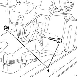
1. Undo the bolts (1a) and remove the support on the engine for the engine component reaction rod and intermediate driveshaft (1b) complete with single auxiliary drivebelt mobile tensioner (1c).
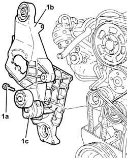
1. Remove the locating bushes.
2. Fit the right brackets for supporting the engine on the service stand.
| Name | Country | |
|---|---|---|
| 2 | Brackets | 1.861.001.141 |
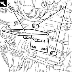
1. Position the engine (1a) on the overhaul stand (1b) using the special brackets, then release it from the hydraulic lift.
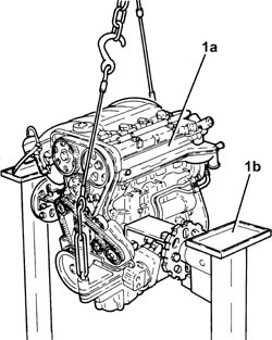
Secure and support the engine using a hydraulic hoist fitted with suitable chains.
Undo the fastenings and remove the engine complete with mounting brackets from the service stand.
Undo the fixings and remove the mounting brackets from the engine and put them down.
| Name | Country | |
|---|---|---|
| Brackets | 1.861.001.141 |
Refit the locating bushes in their seats.
1. Place the mounting on the engine for the reaction rod and various engine components (1a), complete with the moving tensioner for the single drive belt (1b) back in its housing and secure it by tightening the bolts (1c) and (1d) to the recommended torque.
| Fastening | Component | Ø | Value (daNm) | |
|---|---|---|---|---|
| 1c | Bolt | ENGINE LINK AND VARIOUS COMPT.MOUNTS | M10 | (Engine crankcase side) 4.5 - 5.5 |
| Fastening | Component | Ø | Value (daNm) | |
|---|---|---|---|---|
| 1d | Bolt | ENGINE LINK AND VARIOUS COMPT.MOUNTS | M8 | (Engine crankcase side) 2.3 - 2.8 |
2. Tighten the bolt securing the intermediate drive shaft mounting to the oil sump.
| Fastening | Component | Ø | Value (daNm) | |
|---|---|---|---|---|
| 2 | Bolt | ENGINE LINK AND VARIOUS COMPT.MOUNTS | M8 | (Crankcase sump side) 2.3 ÷ 2.8 |
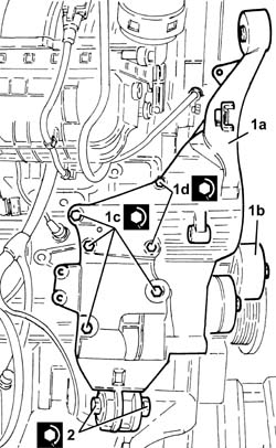
Place the modular intake manifold mounting
Place the bracket back in its housing and secure it using the bolts.
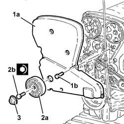
1. Fit the upper protective timing gear cover (1a) and secure using the bolts (1b).
2. Place the engine components single drive belt fixed tensioner (2a) back in its housing and secure by tightening bolt (2b) to the recommended torque.
| Fastening | Component | Ø | Value (daNm) | |
|---|---|---|---|---|
| 2b | Bolt | FIXED SINGLE SERVICE BELT TENSIONER | M8 | 2.2 ÷ 2.8 |
3. Place the engine components single drive belt fixed tensioner plug back in its seating.
1. Refit the power steering pump (1a) in its seating and tighten its bolts (1b) to the specified torque.
| Fastening | Component | Ø | Value (daNm) | |
|---|---|---|---|---|
| 1b | Bolt | POWER STEERING PUMP | M8 | (Support side) 2.3 ÷ 2.8 |
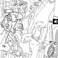
Refit the power steering reservoir, complete with pipe, back in its housing and secure using the bolts.
Connect the pipe from the fluid reservoir to the power assisted steering pump, pump side and tighten the band.
Secure the coolant return pipe to the engine coolant reservoir to the fastenings.
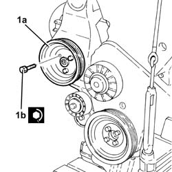
1. Place the power assisted steering pump pulley (1a) back in its housing and fix it tightening the bolts (1b) to the recommended torque.
| Fastening | Component | Ø | Value (daNm) | |
|---|---|---|---|---|
| 1b | Bolt | POWER STEERING PUMP DRIVE PULLEY | M8 | (Power assisted steering pump side) 2.3 ÷ 2.8 |
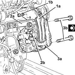
1. Place the alternator protection (1a) back in its housing and secure it with bolt (1b).
2. Place the rear alternator mounting bracket (2a) back in its housing and secure with the bolts (2b).
3. Place the alternator (3a) back in its housing and secure by tightening the bolts (3b) to the recommended torque.
| Fastening | Component | Ø | Value (daNm) | |
|---|---|---|---|---|
| 3b | Bolt | ALTERNATOR ASSEMBLY | M10 | (Support side) 4.4 ÷ 5.5 |
| Fastening | Component | Ø | Value (daNm) | |
|---|---|---|---|---|
| 3b | Bolt | ALTERNATOR ASSEMBLY | M12 | (Support side) 6.3 ÷ 7.7 |
Refit the air conditioner compressor mounting bracket locating bush.
Place the complete engine oil dipstick tube back in its housing and fix it using the bolt.
Place the engine oil dipstick back in its seating.
Refit the catalytic converter, complete with gasket, back in its housing and secure by tightening the nuts to the recommended torque.
| Fastening | Component | Ø | Value (daNm) |
|---|
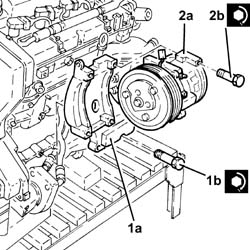
1. Place the air conditioning compressor mounting (1a) back in its housing and secure by tightening the bolts (1b) to the recommended torque.
| Fastening | Component | Ø | Value (daNm) | |
|---|---|---|---|---|
| 2b | Bolt | COMPRESSOR MOUNT (AC) | M10 | (Crankcase side) 4.5 ÷ 5.5 |
2. Refit the air conditioning compressor mounting (2a) back and secure by tightening the bolts (2b) to the recommended torque.
| Fastening | Component | Ø | Value (daNm) | |
|---|---|---|---|---|
| 1b | Bolt | AIR CONDITIONER ASSEMBLY COMPRESSOR | M8 | (Support side) 2.3 ÷ 2.8 |
Adjust the moving tensioner and fit the engine components single drive belt.
Release the engine from the hydraulic lift.
1. Secure and support the engine (1a) using a hydraulic hoist (1b) fitted with suitable chains (1c).
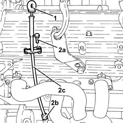
1. Release and rmove the engine oil dipstick.
2. Undo the bolt (2a) and the connector (2b), then remove the engine oil dipstick pipe (2c).
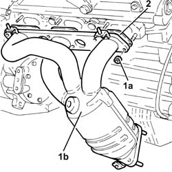
1. Undo the nuts (1a) and remove the left exhaust manifold with the catalytic preconverter (1b) incorporated.
2. Remove the gaskets.
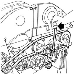
1. Use a spanner on the moving tensioner and remove the single drive belt to loosen the belt tension.
2. Remove the engine components single drive belt.
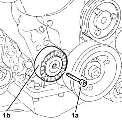
1. Undo the bolt (1a) and remove the fixed single drive belt tensioner (1b).
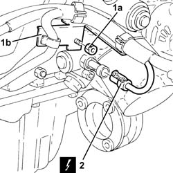
1. Undo the nut (1a) fixing the electrical wiring mounting bracket (1b).
2. Disconnect the electrical connection for the insufficient engine oil pressure sensor.
| Name | Connector | |
|---|---|---|
| 2 | Engine oil pressure sensor | See K30 ENGINE OIL PRESSURE SENSOR SWITCH ( CONNECTORS ) |
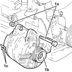
1. Undo the bolts (1a) and remove the alternator (1b) complete with electrical wiring (1c).
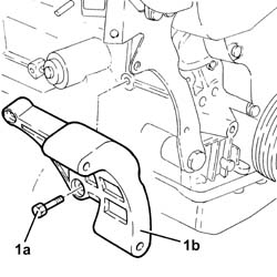
1. Undo the bolts (1a) and remove the alternator mounting (1b).
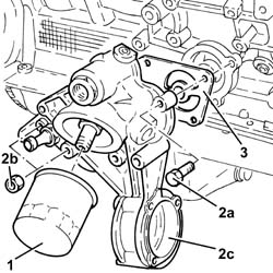
1. Remove the engine oil filter using a suitable tool.
2. Undo the bolts (2a) and the nuts (2b) and remove the engine oil filter/intermediate driveshaft mounting (2c).
3. Remove the gasket.
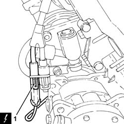
1. Disconnect the electrical connection for the air conditioning compressor electromagnet coupling.
| Name | Connector | |
|---|---|---|
| 1 | Air conditioning compressor engagement electro-magnet | See L20 AIR CONDITIONING COMPRESSOR ENGAGEMENT ELECTRO-MAGNET ( CONNECTORS ) |
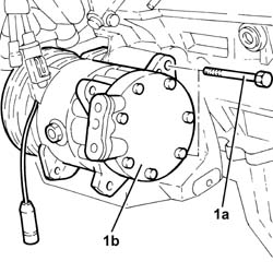
1. Undo the bolts (1a) and remove the air conditioning compressor (1b).
1. Fit the brackets for supporting the engine on the service stand.
| Name | Country | |
|---|---|---|
| 1 | Brackets | 1.820.145.000 |
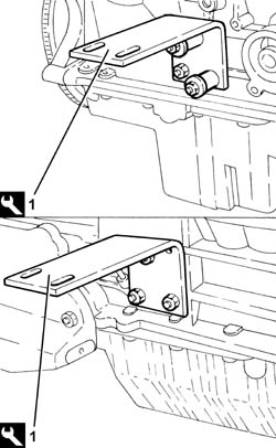
Position the engine on the overhauling stand using the special brackets, then release it from the hydraulic lift.
Secure and support the engine using a hydraulic hoist fitted with suitable chains.
Undo the fastenings and remove the engine complete with mounting brackets from the service stand.
Undo the fixings and remove the mounting brackets from the engine and put them down.
1. Place the air conditioning compressor (1a) back in its housing and secure it tightening the bolts (1b) to the recommended torque.
| Fastening | Component | Ø | Value (daNm) | |
|---|---|---|---|---|
| 1b | Bolt | AIR CONDITIONER ASSEMBLY COMPRESSOR | M10 | (Support side) 4.5 ÷ 5.5 |
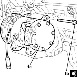
Connect the electrical connection to the air conditioning compressor electromagnet coupling.
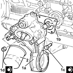
1. Place the engine oil filter/intermediate driveshaft mounting (1a), complete with gasket (1b) back in its housing and secure it tightening the bolts (1c) and the nuts (1d) to the recommended torque.
| Fastening | Component | Ø | Value (daNm) | |
|---|---|---|---|---|
| 1c | Bolt | DRIVE SHAFT OIL FILTER/BEARING MOUNT | M8 | (Engine crankcase side) 2.3 ÷ 2.8 |
| Fastening | Component | Ø | Value (daNm) | |
|---|---|---|---|---|
| 1d | Nut | DRIVE SHAFT OIL FILTER/BEARING MOUNT | M8 | (Engine crankcase side) 2.3 ÷ 2.8 |
2. Fit the engine oil filter and tighten it fully by hand.
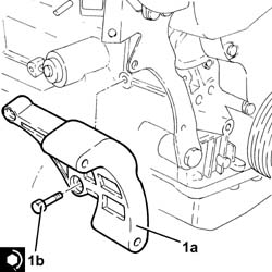
1. Place the alternator mounting (1a) back in its housing and secure it tightening the bolts (1b) to the recommended torque.
| Fastening | Component | Ø | Value (daNm) | |
|---|---|---|---|---|
| 1b | Bolt | ALTERNATOR SUPPORT | M8 | (Engine crankcase side) 1.9 ÷ 2.3 |
| Fastening | Component | Ø | Value (daNm) | |
|---|---|---|---|---|
| 1b | Bolt | ALTERNATOR SUPPORT | M10 | (Engine crankcase side) 4.3 ÷ 5.3 |
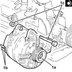
1. Place the alternator (1a), complete with electrical wiring (1b), back in its housing and secure it tightening the bolts (1c) to the recommended torque.
| Fastening | Component | Ø | Value (daNm) | |
|---|---|---|---|---|
| 1c | Bolt | ALTERNATOR ASSEMBLY | M8 | (Support side) 2.3 ÷ 2.8 |
Connect the electrical connection to the engine oil pressure warning sensor.
Tighten the nut securing the electrical wiring mounting bracket.
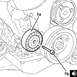
1. Place the engine components single drive belt fixed tensioner (1a) back in its housing and fix it tightening the bolts (1b) to the recommended torque.
| Fastening | Component | Ø | Value (daNm) | |
|---|---|---|---|---|
| 1b | Bolt | FIXED SINGLE SERVICE BELT TENSIONER | M8 | 2.3 ÷ 2.8 |
Place the single engine components belt back in its housing keeping the moving tensioner in a slack belt position using a suitable spanner.
1. Place the left exhaust manifold with the catalytic preconverter (1a) incorporated complete with gaskets (1b) back in its housing and secure it tightening the nuts (1c) to the recommended torque.
| Fastening | Component | Ø | Value (daNm) | |
|---|---|---|---|---|
| 1c | Nut | EXHAUST MANIFOLD/S | M8 | (Cylinder head side) 2.4 ÷ 3.0 |
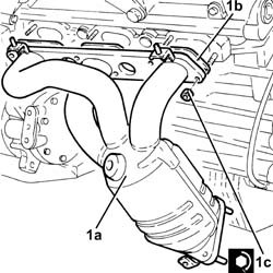
Place the complete engine oil dipstick tube back in its housing and fix it using the connector and the bolt.
Place the engine oil dipstick back in its seating.
Release the engine from the hydraulic lift.
Secure and support the engine using a hydraulic hoist fitted with suitable chains.
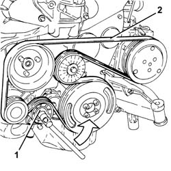
1. Use a spanner, in an anti-clockwise direction, on the moving tensioner to loosen the tension of the engine components single drive belt.
2. Remove the single drive belt.
1. Disconnect the electrical connection for the air conditioning compressor.
| Name | Connector | |
|---|---|---|
| 1 | Air conditioning compressor engagement electro-magnet | See L20 AIR CONDITIONING COMPRESSOR ENGAGEMENT ELECTRO-MAGNET ( CONNECTORS ) |
2. Undo the bolts (2a) and remove the air conditioning compressor (2b).
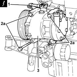
1. Undo the bolts (1a) and remove the air conditioning compresor mounting (1b).
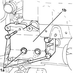
1. Disconnect the electrical connections from the alternator.
| Name | Connector | |
|---|---|---|
| 1 | Alternator | See A10 ALTERNATOR |
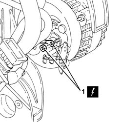
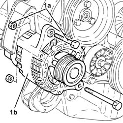
1. Undo the bolts (1a) and remove the alternator (1b).
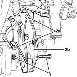
1. Undo the bolt securing the intermediate drive shaft mounting to the crankcase oil sump.
2. Undo the bolts (2a) and remove the intermediate drive shaft mounting (2b) complete with upper alternator bracket (2c).
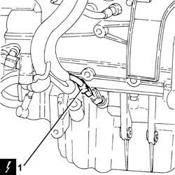
1. Disconnect the electrical connection for the engine oil level sensor.
| Name | Connector | |
|---|---|---|
| 1 | Engine oil level sensor | See K32 ENGINE OIL LEVEL SENSOR |
1. Fit the brackets for positioning the engine on the overhauling stand.
| Name | Country | |
|---|---|---|
| 1 | Brackets | 1.861.001.139 |
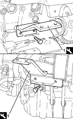
1. Position the engine on the overhauling stand using the hydraulic lift.
Fasten the mounting brackets to the overhaul stand.
Release the engine from the hydraulic lift fastenings.
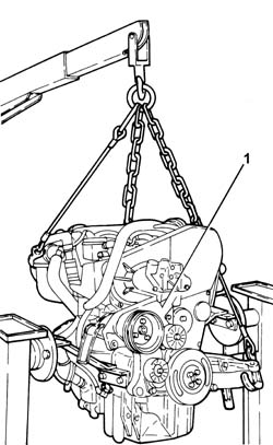
Secure and support the engine using a hydraulic hoist fitted with suitable chains.
Undo the fixings and remove the engine complete with mounting brackets.
Remove the brackets for positioning the engine on the overhauling stand.
| Name | Country | |
|---|---|---|
| Brackets | 1.861.001.139 |
Connect the electrical connection to the engine oil level sensor.
1. Refit intermediate drive shaft (1a) complete with upper alternator mount bracket (1b) and secure it by tightening bolts (1c) to the specified torque.
| Fastening | Component | Ø | Value (daNm) | |
|---|---|---|---|---|
| 1c |
2. Tighten the bolt securing the intermediate drive shaft mounting to the oil sump to the recommended torque.
| Fastening | Component | Ø | Value (daNm) | |
|---|---|---|---|---|
| 2 |
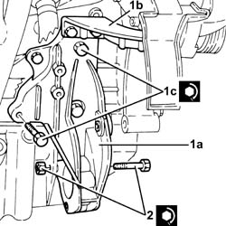
1. Place the alternator (1a) back in its housing and fix it tightening the bolts (1b) to the recommended torque.
| Fastening | Component | Ø | Value (daNm) | |
|---|---|---|---|---|
| 1b |
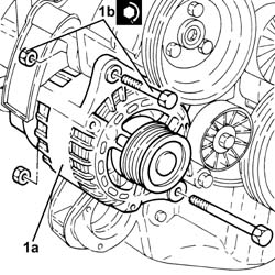
Connect the electrical connection to the alternator.
1. Place the air conditioning compressor mounting (1a) back in its housing and fix it tightening the bolts (1b) to the recommended torque.
| Fastening | Component | Ø | Value (daNm) | |
|---|---|---|---|---|
| 1b |
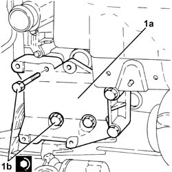
1. Place the air conditioning compressor (1a) back in its housing and secure it tightening the bolts (1b) to the recommended torque.
| Fastening | Component | Ø | Value (daNm) | |
|---|---|---|---|---|
| 1b |
2. Connect the electrical connection to the air conditioner compressor.
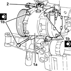
Fit the single engine component belt by adjusting the moving tensioner using a wrench.
Release the engine from the hydraulic lift fastenings.
Secure and support the engine for hoisting using a hydraulic hoist fitted with suitable chains.
Fit the engine on the overhauling stand using suitable tools.
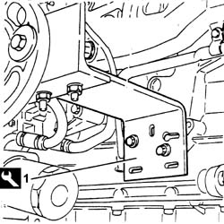
1. It is possible to use the tool to support the engine on the overhauling stand.
| Name | Country | |
|---|---|---|
| 1 | Brackets | 1.820.145.000 |
Release the engine from the hoist.
Secure and support the engine using a hydraulic hoist fitted with suitable chains.
Undo the fixings and remove the engine complete with supporting tools.
Undo the fixings and remove the supporting tools from the engine, then put them down.
Parts & tools for this job Staging For 2003 Alfa Romeo GT
- PARTEngine gasket setSearch: Alfa Romeo GT 2003 engine gasket set
- TOOLTorque wrenchSearch: 3/8 inch torque wrench
- TOOLFeeler gauge setSearch: feeler gauge set
Links open Amazon search results in a new tab. As an Amazon Associate I earn from qualifying purchases.