
Introduction - timing system
- Make
- Alfa Romeo
- Model
- 159 Factory Service Manual
- Year
- 2005–2011
- Section
- Timing system › Introduction - timing system
INTRODUCTION - TIMING SYSTEM
Technical specifications
The timing system comprises a primary chain operated by the crankshaft ring gear which transmits the power to two intermediate ring gears each of which, in turn, controls a secondary chain that activates the inlet and exhaust camshaft ring gears for the respective bank.
The primary chain slides on two fixed guides and a moving guide that acts as a tensioner because it is connected to a hydraulic tensioner.
Special oil jets lubricate the moving timing system components.
The secondary chains are each guided by a fixed pad and tensioned by a moving pad thrust by a hydraulic tensioner.
Chain, gear and reference assembly for timing system
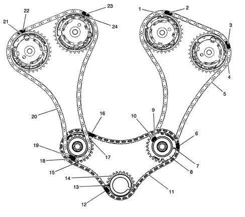
1. Reference at left inlet camshaft gear for left secondary chain
2. Reference at left secondary chain for left inlet camshaft gear
3. Reference at left exhaust camshaft gear
4. Reference at left secondary chain for left exhaust camshaft gear
5. Left secondary chain
6. Reference at primary chain for left intermediate gear
7. Reference at left intermediate gear for primary chain
8. Left intermediate gear
9. Reference at left secondary chain for left intermediate gear
10. Left intermediate gear window for left secondary chain
11. Primary chain
12. Reference at primary chain for crankshaft gear
13. Reference at crankshaft gear for primary chain
14. Crankshaft gear for primary chain
15. Right intermediate gear
16. Reference at primary chain for right intermediate gear
17. Reference at right intermediate gear for primary chain
18. Reference/window at right intermediate gear for right secondary chain
19. Reference at right secondary chain for right intermediate gear
20. Right secondary chain
21. Reference at right exhaust camshaft gear for right secondary chain
22. Reference at right secondary chain for right exhaust camshaft gear
23. Reference at right secondary chain for right inlet camshaft gear
24. Reference at right inlet camshaft gear for right secondary chain
Timing system crankshaft gear
The gear fitted on the crankshaft has the function of transmitting power from the crankshaft to the timing system kinematic chain; it has inverted teeth and works on the main timing chain which also has inverted teeth.
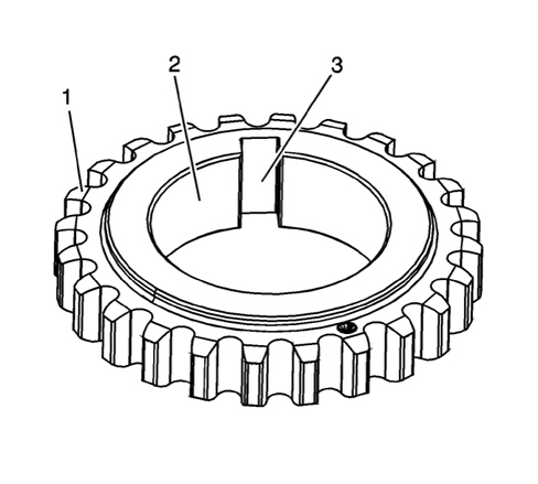
1. Main chain teeth
2. Crankshaft internal matching surface
3. Housing for key
Camshaft drive gears
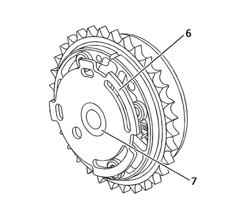
The four camshaft drive gears, with the rear view (camshaft side) and the front view (timing side) for the individual gear illustrated in the diagram, incorporate the hydraulic actuators that allow the timing of the four camshafts (two inlet and two exhaust) to be varied continuously.
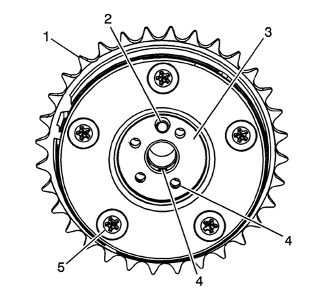
1. Ring gear
2. Camshaft bearing housing
3. Camshaft matching flange
4. Oil ports
5. Bolts
6. Timing sensor wheel
7. Camshaft gear fastening bolt housing
Idler intermediate gears
The two intermediate gears have the task of receiving the drive from the crankshaft by means of the primary timing chain and transmitting it to the camshaft drive gears by means of the secondary timing chain.
There are two toothed ring gears to carry out this function; the larger ring gear has inverted teeth and works on the primary timing chain (which also has inverted teeth), whilst the smaller ring gear has normal teeth and works on the secondary timing chain.
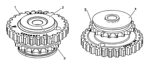
1. Main chain teeth
2. Bearing cover surface
3. Fixing bolt housing surface
4. Crankcase side bearing cover surface
5. Secondary chain teeth
Timing drive chains
The primary drive chain is made with inverted teeth and the gear on the crankshaft also has inverted teeth; the intermediate gear has inverted teeth for connection with the primary chain and a coil with standard teeth for connection with the standard type secondary chain.
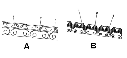
A. Secondary chain
B. Primary chain
1. Rollers
2. Mesh
3. pins
4. Inner mesh
The timing chains have the task of transmitting the power between the various timing gears; they also have timing reference markings on the outer mesh.
Hydraulic tensioners
All the hydraulic tensioners are fitted on the crankcase or the head with a gasket in between that has the task of keeping an oil reserve inside the tensioner to ensure correct operation during starting.
Primary chain hydraulic tensioner
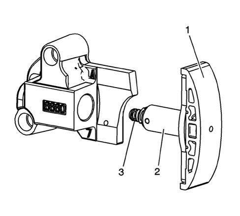
1. Pad
2. Piston
3. Reset
Secondary chain hydraulic tensioners
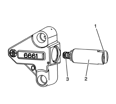
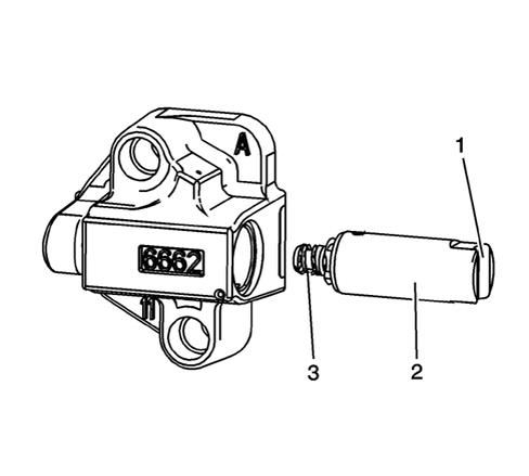
1. Pad contact housing
2. Piston
3. Reset
SPECIFICATIONS
The control is direct, by means of a toothed belt (1) tensioned by an automatic tensioner (2) that does not require maintenance operations for tensioning. A cover, in three parts, protects the toothed belt from dust and from liquid that could cause premature wear.
The routing of the toothed belt has been designed to allow replacement without having to remove the timing side power unit support (4).
The driven toothed pullies are incorporated in the continuous variation timing system actuators.
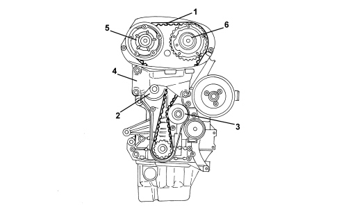
1. Toothed timing drive belt
2. Automatic tensioner
3. Fixed tensioner
4. Power unit rigid support
5. Inlet side toothed driven pulley
6. Exhaust side toothed driven pulley
Parts & tools for this job Staging For 2005 Alfa Romeo 159
- PARTEngine gasket setSearch: Alfa Romeo 159 2005 engine gasket set
- TOOLTorque wrenchSearch: 3/8 inch torque wrench
- TOOLFeeler gauge setSearch: feeler gauge set
Links open Amazon search results in a new tab. As an Amazon Associate I earn from qualifying purchases.