
Variable geometry turbocharger r r
- Make
- Alfa Romeo
- Model
- 159 Factory Service Manual
- Year
- 2005–2011
- Section
- Engine supercharging system › Variable geometry turbocharger r r
VARIABLE GEOMETRY TURBOCHARGER R R
Removing
Op. 1016A10 SOUND-PROOFING COVER - R.R
Op. 1048A51 TURBOCHARGER RIGID AIR INLET HOSE - R.R.
Op. 1048A42 SLEEVE FROM FLOW METER TO TURBO CHARGER AIR INLET PIPE - R + R
Op. 0010T84 COOLANT FOR AIR CONDITIONING SYSTEM - DEHYDRATE AND REPRESSURIZE
Op. 7055B54 UNDER ENGINE PROTECTION/GUARD - R.R.
Op. 4450B04 RIGHT FRONT WHEEL - R.R
Op. 7055B91 RIGHT FRONT WHEEL ARCH LINER - R.R.
Op. 1092C26 BELT FROM AIR CONDITIONER COMPRESSOR DRIVING POWER STEERING PUMP - R + R
Op. 1092B68 BELT FROM A/C COMPRESSOR TO ALTERNATOR DRIVE - R + R
Op. 5040A20 AIR CONDITIONING COMPRESSOR - R+R - INCLUDES FLUID LEVEL CHECK AND TOP UP IF NECESSARY
Op. 1072C44 EXHAUST MANIFOLD HEAT SHIELD - R+R
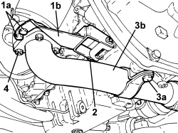
1. Unscrew bolts (1a) securing bracket (1b) to the catalytic converter.
2. Undo the bolt securing bracket (1b) to the engine oil sump and remove it.
3. Undo bolt (3a) securing exhaust pipe (3b) to the engine oil sump.
4. Undo the nuts securing exhaust pipe (3b) to the catalytic converter and move it to one side.
- Remove the gasket.
1. Unscrew the exhaust gas temperature sensor from the catalytic converter.
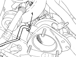
1. Undo the engine oil delivery pipe connector, engine crankcase side.
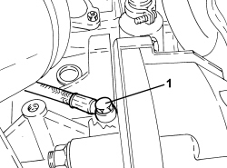
1. Undo the bolts securing the engine oil return pipe, engine oil sump side.
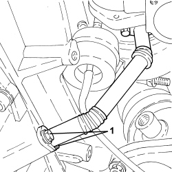
1. Unscrew bolts (1a) securing exhaust gas pipe (1b) for the EGR.
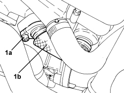
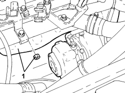
1. Undo the nuts securing the exhaust manifold to the cylinder head and remove it complete with turbocharger and catalytic converter.
- Remove the gasket.
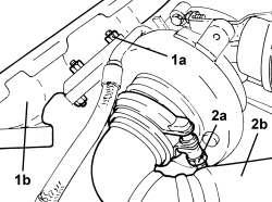
1. Undo nuts (1a) securing exhaust manifold (1b) to the turbocharger and remove it.
2. Loosen collar (2a) and disconnect catalytic converter (2b) from the turbocharger.
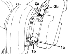
1. Undo connector (1a) and remove turbocharger engine oil supply pipe (1b).
2. Undo bolts (2a) and remove turbocharger oil return pipe (2b).
Refitting
- Place the turbocharger engine oil return pipe back in position and tighten the turbocharger-side bolts to the recommended torque.
| Component | Fastening | dia | Value (daNm) | Validity |
|---|---|---|---|---|
| Engine oil supply pipe from turbocharger | Bolt | M6 | (turbocharger side) 0.8 - 1.0 | 2.4 JTD 20V |
- Place the engine oil supply pipe back in position and tighten the turbocharger-side connector to the recommended torque.
| Component | Fastening | dia | Value (daNm) | Validity |
|---|---|---|---|---|
| Engine oil supply pipe to turbocharger | Connector | M10 | (turbocharger side) 1.5 | 1.9 JTD 8V 1.9 JTD 16V 2.4 JTD 20V |
- Connect the catalytic converter to the turbocharger and fasten it using the collar.
- Tighten the nuts securing the exhaust manifold to the turbocharger to the recommended torque.
| Component | Fastening | dia | Value (daNm) | Validity |
|---|---|---|---|---|
| Exhaust manifold | Nut | M8 | (turbocharger side) 2.3 - 2.8 | 2.4 JTD 20V |
- Fit a new gasket onto the exhaust manifold.
- Place the exhaust manifold complete with turbocharger and catalytic converter back in position and secure it to the cylinder head by tightening the nuts to the recommended torque.
| Component | Fastening | dia | Value (daNm) | Validity |
|---|---|---|---|---|
| Exhaust manifold | Nut | M8 | (cylinder head side) 2.3 - 2.8 | 2.4 JTD 20V |
- Tighten the bolts securing the exhaust gas pipe for the E.G.R. to the recommended torque.
| Component | Fastening | dia | Value (daNm) | Validity |
|---|---|---|---|---|
| Exhaust gas pipe for E.G.R. | Bolt | M8 | (exhaust manifold side) 2.3 - 2.8 | 2.4 JTD 20V |
- Tighten the bolts securing the engine oil return pipe, oil sump side, to the specified torque.
| Component | Fastening | dia | Value (daNm) | Validity |
|---|---|---|---|---|
| Engine oil supply pipe from turbocharger | Bolt | M6 | (engine block side) 0.8 - 1.0 | 2.4 JTD 20V |
- Tighten the engine oil delivery pipe connector, engine crankcase side, to the recommended torque.
| Component | Fastening | dia | Value (daNm) | Validity |
|---|---|---|---|---|
| Engine oil supply pipe to turbocharger - crankcase side | Connector | M12 | 2.2 ÷ 2.7 | 1.9 JTD 8V 2.4 JTD 20V |
- Tighten the exhaust gas temperature sensor onto the catalytic converter.
- Place the exhaust pipe complete with new gasket back in position and secure it to the catalytic converter by tightening the nuts to the recommended torque.
| Component | Fastening | dia | Value (daNm) | Validity |
|---|---|---|---|---|
| Intermediate exhaust pipe with flexible section | Nuts | M8 | (catalytic converter side) 2.2 - 2.6 | 1.9 JTD 8V 1.9 JTD 16V 2.4 JTD 20V |
- Tighten the bolt securing the exhaust pipe to the engine oil sump.
- Place the bracket back in position and secure the bolt fastening it to the oil sump.
- Tighten the bolts securing the bracket to the catalytic converter.
Op. 1072C44 EXHAUST MANIFOLD HEAT SHIELD - R+R
Op. 5040A20 AIR CONDITIONING COMPRESSOR - R+R - INCLUDES FLUID LEVEL CHECK AND TOP UP IF NECESSARY
Op. 1092B68 BELT FROM A/C COMPRESSOR TO ALTERNATOR DRIVE - R + R
Op. 1092C26 BELT FROM AIR CONDITIONER COMPRESSOR DRIVING POWER STEERING PUMP - R + R
Op. 7055B91 RIGHT FRONT WHEEL ARCH LINER - R.R.
Op. 4450B04 RIGHT FRONT WHEEL - R.R
Op. 7055B54 UNDER ENGINE PROTECTION/GUARD - R.R.
Op. 0010T84 COOLANT FOR AIR CONDITIONING SYSTEM - DEHYDRATE AND REPRESSURIZE
Op. 1048A42 SLEEVE FROM FLOW METER TO TURBO CHARGER AIR INLET PIPE - R + R
Parts & tools for this job Staging For 2005 Alfa Romeo 159
- PARTEngine gasket setSearch: Alfa Romeo 159 2005 engine gasket set
- TOOLTorque wrenchSearch: 3/8 inch torque wrench
- TOOLFeeler gauge setSearch: feeler gauge set
Links open Amazon search results in a new tab. As an Amazon Associate I earn from qualifying purchases.