
Introduction - engine lubrication
- Make
- Alfa Romeo
- Model
- 159 Factory Service Manual
- Year
- 2005–2011
- Section
- Engine lubrication › Introduction - engine lubrication
INTRODUCTION - ENGINE LUBRICATION
OIL PUMP
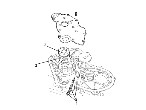
1. Pressure regulator valve
2. Stator
3. Rotor
The oil pump is built into the timing chain casing.
It is operated by the crankshaft via a torsional vibration damper. The pressure regulator valve is accessible from outside and opens throughout a pressure range from 4 to 6 bar.
The two main lubrication channels are fied via channels cast into the cylinder block. These main channels feed the entire engine lubrication system, bearings, cylinder head, chain and balancing shafts.
OIL FILTER
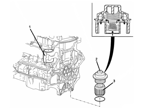
1. Oil filter housing
2. Oil filter cover
3. Filter cartridge
The oil filter cartridge seat is cast into the engine block.
The oil filter consists of a paper cartridge. The filter cover, which also contains the bypass valve, is screw-in.
ENGINE OIL/WATER HEAT EXCHANGER
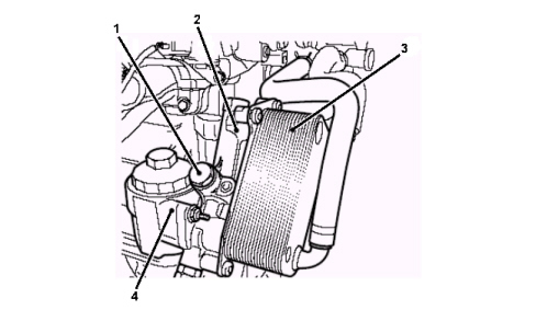
1. Engine oil thermostat
2. Oil filter adapter housing
3. Exchanger
4. Oil filter housing
COMPOSITION
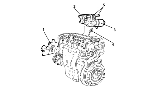
1. Oil pump
2. Oil filter cartridge mount
3. Oil filter
4. Engine oil level sensor
5. Water/oil heat exchanger
COMPOSITION
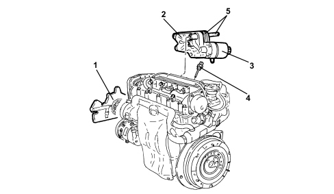
1. Oil pump
2. Oil filter cartridge mount
3. Oil filter
4. Engine oil level sensor
5. Water/oil heat exchanger
Lubrication system
Oil pump
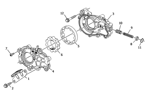
1. Main timing chain lower guide
2. Main timing chain lower guide bolt
3. Oil pump casing
4. Pump cover
5. Driven gear
6. engine gear
7. Cover fixing bolts
8. Pressure regulator valve cap
9. Pressure regulator valve spring
10. Pressure regulator valve
11. Pressure regulator valve cap retaining ring
12. Oil pump fixing bolts
Function:
the oil pump ensures the circulation of the flow rate required for the forced lubrication of the various moving engine components.
Location:
the oil pump is fitted at the front of the crankcase (timing side) on the same axis as the crankshaft.
Specifications:
it is operated directly by the crankshaft through a key; the pressure regulating valve is housed on the pump ensuring the system operating pressure (between 4 and 6 bar); the pump gears have outer (engine) teeth and inner (driven) teeth; the flow rate varies with the number of revs.
The pump draws in oil by means of the lower channel in the cylinder block and sends the pressurized oil flow via the channel in the left side of the cylinder block where the filter assembly is fitted.
Oil filter and cooling
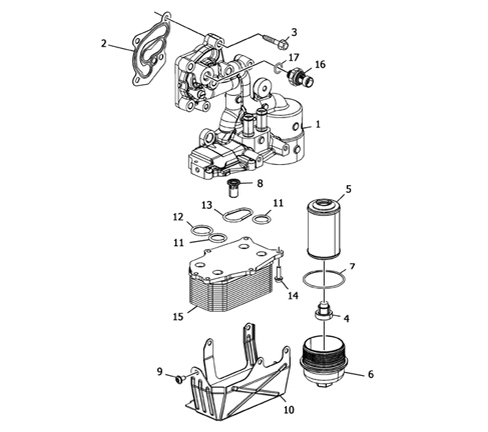
1. Oil filter mounting
2. Filter mounting gasket
3. Filter mounting bolts
4. Filter by-pass valve
5. Oil filter cartridge
6. Filter cartridge cover
7. O-ring
8. Heat exchanger by-pass valve
9. Heat exchanger protection fixing bolt
10. Heat exchanger protection
11. Heat exchanger O-ring (small)
12. Heat exchanger O-ring (large)
13. Heat exchanger O-ring (oval)
14. Heat exchanger bolts
15. Exchanger
16. Engine oil pressure sensor
17. Engine oil sensor O-ring
The filter mounting is fitted on the left side of the crankcase; the filter cartridge is located inside held in place by a cover bolted onto the lower part of the mounting with the seal ensured by an O-ring; the filter by-pass valve is located on the cover.
The oil pressure sensor, the water-oil heat exchanger and a by-pass valve for the exchanger are located on the filter mounting.
The oil coming from the oil pump is sent via the exchanger and filtered by the filter cartridge, after which it continues on its journey through the engine ducts supplying the entire engine lubrication circuit, bearings, pistons, cylinder heads and timing chains.
Engine lubrication system diagram
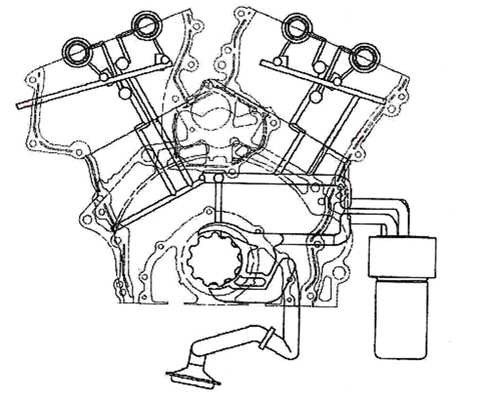
The lubrication of the moving engine components is the forced type with the lubricating oil circulating by means of the oil pump on the same axis as the crankshaft; the oil is taken by the oil sump from the pump and sent via a channel on the left side of the crankcase to the oil filter; from the filter the oil flows, via the main duct in the crankcase, and then via two ducts that rise towards the left cylinder head and then go down to lubricate the crankshaft main journals and crank pins and two ducts that rise to lubricate the left cylinder head; having reached the cylinder heads the oil then lubricates the camshafts and supplies the hydraulic tappets and the phase transformers; the oil then returns to the sump by means of ports that go from the cylinder head to the sump.
ENGINE OIL PUMP
The oil pump module is incorporated in the engine block front cover and is operated directly by the crankshaft. The oil supply is regulated by a pressure relief valve.
The two main lubrication ducts are supplied by means of channels produced through fusion behind the engine block. These main ducts supply the entire engine lubrication system, bearings, cylinder head and camshaft timing variation system.
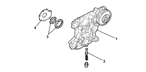
1. Oil pump - crankcase front cover integrated module
2. Relief valve
3. Oil pump rotors
4. Oil pump rear cover
OIL FILTER
The oil filter cartridge housing is part of a compact, aluminium alloy module which includes a water-oil heat exchanger.
Fitting the module on the left side of the engine block allows a direct connection with the water circuit assisting the rapid heating of the oil whilst the engine is warming up and a reduced oil pressure loss.
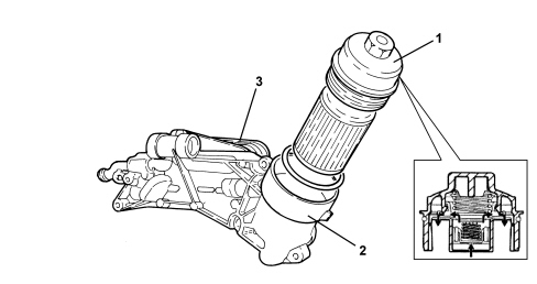
1. Engine oil filter cover
2. Engine oil filter mounting
3. Engine oil cooling heat exchanger
Parts & tools for this job Staging For 2005 Alfa Romeo 159
- PARTEngine gasket setSearch: Alfa Romeo 159 2005 engine gasket set
- TOOLTorque wrenchSearch: 3/8 inch torque wrench
- TOOLFeeler gauge setSearch: feeler gauge set
Links open Amazon search results in a new tab. As an Amazon Associate I earn from qualifying purchases.