
Single cylinder head, removed - overhaul
- Make
- Alfa Romeo
- Model
- 159 Factory Service Manual
- Year
- 2005–2011
- Section
- Cylinder head/s › Single cylinder head, removed - overhaul
SINGLE CYLINDER HEAD, REMOVED - OVERHAUL
Removing
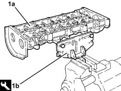
1. Position the cylinder head in the vice using the support tool.
| Tool | Description | Function | Validity |
|---|---|---|---|
| 1860470000 | Support | Overhaul cylinder head |
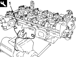
1. Disconnect the pipes (1a) and remove the three-way connector (1b).
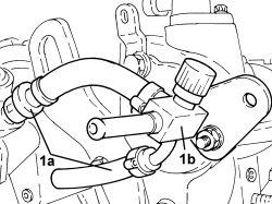
1. Undo the nuts (1a) and remove the lifting bracket (1b).
2. Undo the fastenings (2a) and remove the pressure pump (2b).
3. Undo the bolts (3a) and remove the two timing sensors (3b).
4. Undo the fastenings and remove the camshaft rear cap cover.
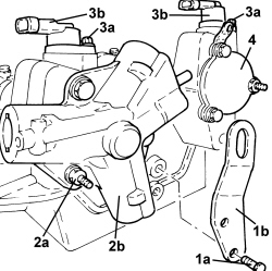
- Mark the position of the camshafts.
1. Undo the bolts (1a) and remove the camshaft caps (1b).
The rear inlet side camshaft cap has silicon sealant therefore a plastic hammer should be used for the removal.
2. Remove the camshafts.
- Remove the camshaft front oil seals.
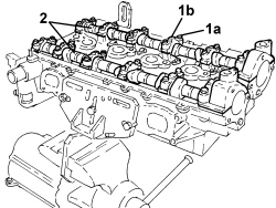
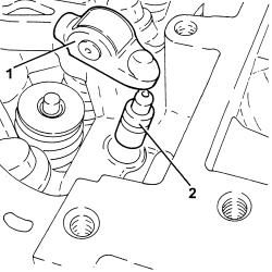
1. Remove the tappet rocker arms.
2. Remove the hydraulic tappets.
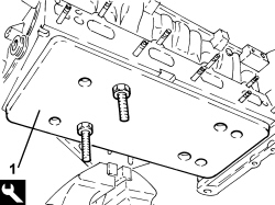
1. Fit the valve support under the head.
| Tool | Description | Function | Validity |
|---|---|---|---|
| 2000003400 | Support | Valve support | 1.9 JTS 2.2 JTS |
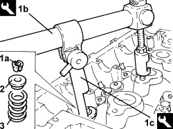
1. Fit the cotters (1a) using the tools (1b) and (1c).
2. Remove the valve upper shim.
3. Remove the valve spring.
| Tool | Description | Function | Validity |
|---|---|---|---|
| 1821058000 | Lever | Valve spring compression lever | 1.9 JTS 2.2 JTS 1.9 JTD 8V |
| Tool | Description | Function | Validity |
|---|---|---|---|
| 2000002700 | Chamber | Valve spring compression | 1.9 JTS 2.2 JTS |
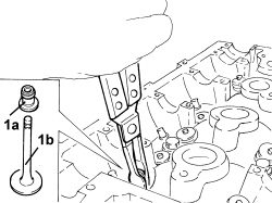
1. Remove the valve guide oil seals (1a) with built in lower shim and the valve (1b).
Refitting
- Clean the contact surfaces between the cylinder head and the crankcase.
COMBUSTION CHAMBER WITH THE POINT FOR MEASURING THE DEPTH SHOWN
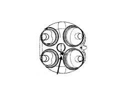
- The lower cylinder head plane can be refaced if the flatness is not within the recommended values.
| Measurement | Value | Validity | ||
|---|---|---|---|---|
| Cylinder head lower surface flatness | 0.05 - 0.15 mm | 1.9 JTS 2.2 JTS | ||
- The refacing does not have to be carried out for lower flatness values.
- The refacing is not permitted for higher flatness values.
- After refacing it is necessary to check that the minimum depth for each combustion chamber is 12.75 mm (at the point shown in the diagram above) in order to guarantee the minimum combustion chamber volume.
- Check that the valves do not show signs of grooves or seizing.
- Check that the diameter of the valve stems corresponds to the recommended figures; if not, replace the worn valves.
| Measurement | Value | Validity |
|---|---|---|
| Inlet valve stem diameter | 5.900 - 5.940 mm | 1.9 JTS 2.2 JTS |
| Measurement | Value | Validity |
|---|---|---|
| Exhaust valve stem diameter | 5.900 - 5.940 mm | 1.9 JTS 2.2 JTS |
- Check that the diameter of the valve head corresponds to the recommended figures; if not, replace the worn valves.
| Measurement | Value | Validity |
|---|---|---|
| Inlet valve head diameter | 34.95 - 35.25 mm | 1.9 JTS 2.2 JTS |
| Measurement | Value | Validity |
|---|---|---|
| Exhaust valve head diameter | 29.95 - 30.25 mm | 1.9 JTS 2.2 JTS |
- Check that the nominal camshaft cam lift corresponds to the recommended figures; if not, replace the worn camshaft.
| Measurement | Value | Validity |
|---|---|---|
| Nominal inlet cam lift | 10.30 mm | 1.9 JTS 2.2 JTS |
| Measurement | Value | Validity |
|---|---|---|
| Nominal exhaust cam lift | 10.30 mm | 1.9 JTS 2.2 JTS |
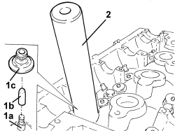
1. Temporarily position the valve (1a) in the seat and fit the tool (1b) for centering the valve guide oil seal (1c) on it.
2. Fit the valve guide oil seal using the tool.
| Tool | Description | Function | Validity |
|---|---|---|---|
| 1860814001 | Shrink disk | Fit valve oil seals | 1.9 JTS 2.2 JTS 1.9 JTD 8V |
| Tool | Description | Function | Validity |
|---|---|---|---|
| 2000002600 | Fitting tool | Valve oil seals | 1.9 JTS 2.2 JTS |
- Position the spring and the upper shim on the valve.
- Place the cotters back in their housings using the tools.
| Tool | Description | Function | Validity |
|---|---|---|---|
| 1821058000 | Lever | Valve spring compression lever | 1.9 JTS 2.2 JTS 1.9 JTD 8V |
| Tool | Description | Function | Validity |
|---|---|---|---|
| 2000002700 | Chamber | Valve spring compression | 1.9 JTS 2.2 JTS |
- Carry out the same operations to refit the remaining bolts.
- Place the camshafts in their housings.
- Place the camshaft caps in their housings and secure them tightening the bolts to the recommended torque.
| Component | Fastening | dia | Value (daNm) | Validity |
|---|---|---|---|---|
| Camshaft rear caps | Bolt | M6 | (cylinder head side) 0.7 - 0.9 | 1.9 JTS 2.2 JTS |
| Component | Fastening | dia | Value (daNm) | Validity |
|---|---|---|---|---|
| Camshaft front/ intermediate caps | Bolt | M8 | (cylinder head side) 1.8 - 2.2 | 1.9 JTS 2.2 JTS |
- Place the two timing sensors in their housings and tighten the bolts to the recommended torque.
| Component | Fastening | dia | Value (daNm) | Validity |
|---|---|---|---|---|
| Phase transformer solenoids | Bolt | M6 | (cylinder head side) 1.0 | 1.9 JTS 2.2 JTS 3.2 JTS |
- Place the pressure pump in position and tighten the fastenings to torque.
| Component | Fastening | dia | Value (daNm) | Validity |
|---|---|---|---|---|
| Pressure pump | Bolt | M6 | 1.0 | 1.9 JTS 2.2 JTS |
- Connect the pipes and fit the three-way fuel connector.
Removing
CYLINDER HEAD EXTENSION
1. Position the cylinder head extension (1a) in a vice using the tool (1b).
| Tool | Description | Function | Validity |
|---|---|---|---|
| 1860470000 | Support | Overhaul cylinder head |
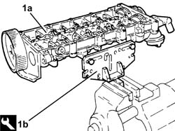
1. Undo the bolts (1a) and remove the engine oil filler (1b).
2. Remove the gasket.
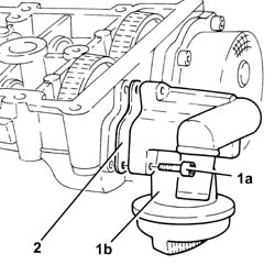
1. Undo the bolts (1a) and remove the vacuum unit (1b).
2. Remove the gasket.
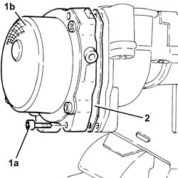
1. Undo the bolt (1a) and remove the cam angle sensor (1b).
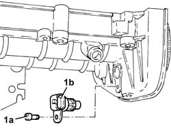
1. Remove the plugs (1a) and fit camshaft timing tools (1b) on the camshaft housing.
Check that the tools are correctly fitted in the housings in the camshafts.
| Tool | Description | Function | Validity |
|---|---|---|---|
| 1870896900 | Template | Engine tuning | 1.9 JTD 16V |
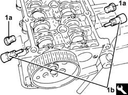
1. Undo the bolts fixing the camshaft gears.
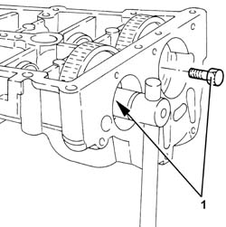
1. Undo the bolt (1a) and remove the exhaust side camshaft toothed drive pulley (1b).
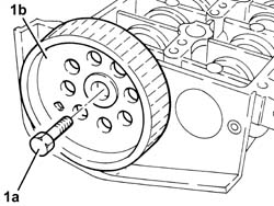
Remove the camshaft timing tools from the cylinder head extension.
| Tool | Description | Function | Validity |
|---|---|---|---|
| 1870896900 | Template | Engine tuning | 1.9 JTD 16V |
1. Wtihdraw the camshafts (1a), as far as necessary and remove the camshaft gears (1b).
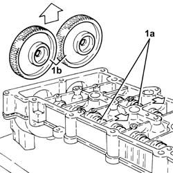
1. Using a suitable drift, extract the inlet side camshaft (1a) and plug (1b).
2. Using a suitable drift, extract the exhaust side camshaft (2a) and oil seal (2b).
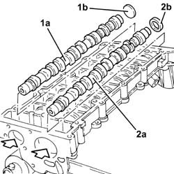
1. Undo and remove the engine oil lubrication duct plugs.
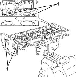
1. Position the cylinder head (1a) in a vice using the tool (1b).
| Tool | Description | Function | Validity |
|---|---|---|---|
| 1860470000 | Support | Overhaul cylinder head |
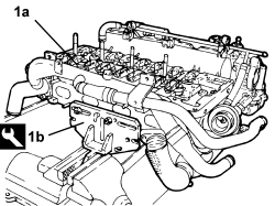
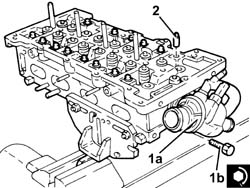
1. Loosen collar (1a), unscrew nut (1b) and bolts (1c), then remove the rigid fluid inlet pipe to the water pump assembly (1d).
- Remove the gasket.
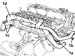
1. Undo the bolts (1a) and (1b) and remove the water/exhaust gas heat exchanger for the E.G.R. system assembly (1c).
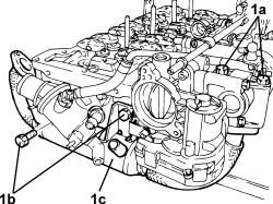
1. Loosen the collar and disconnect the degasing pipe from the thermostat.
1. Undo the nuts (2a) and remove the intake manifold assembly (2b).
- Remove the gasket.
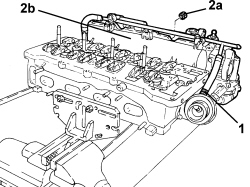
1. Remove the hydraulic tappets.
2. Undo the bolts (2a) and remove the thermostat (2b).
Remove the gasket.
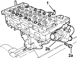
1. Undo the bolts (1a) and remove the water pump (1b).
2. Remove the gasket.
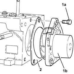
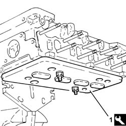
1. Fit a wooden stand on the cylinder head plane to support the valves and secure it using bolts.
| Tool | Description | Function | Validity |
|---|---|---|---|
| 1860804001 | Stand | Removing/refitting valves | 1.8 1.9 JTD 16V |
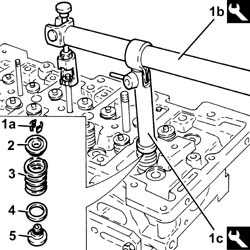
1. Fit the cotters (1a) using the tools (1b) and (1c).
| Tool | Description | Function | Validity |
|---|---|---|---|
| 1860644001 | Lever | Removing/refitting valves | 1.8 1.9 JTD 16V |
| Tool | Description | Function | Validity |
|---|---|---|---|
| 1870890000 | Chamber | Removing/refitting valves | 1.9 JTD 16V |
2. Remove the valve upper shim.
3. Remove the valve spring.
4. Remove the shim (for exhaust valves only).
5. Remove the valve guide oil seal with integrated lower valve shim.
Carry out the same operations on the other valves.
Remove the wooden stand and recover the valves.
| Tool | Description | Function | Validity |
|---|---|---|---|
| 1860804001 | Stand | Removing/refitting valves | 1.8 1.9 JTD 16V |
Remove the lower cylinder head from the support tool.
| Tool | Description | Function | Validity |
|---|---|---|---|
| 1860470000 | Support | Overhaul cylinder head |
Replace the valve guide
Op. 1016E14 VALVE GUIDES IN SINGLE CYLINDER HEAD - REPLACE DURING OP. 1016E10
Refitting
Clean any residues of the old gasket from the lower cylinder head plane.
Check that the flatness of the lower cylinder head plane corresponds to the recommended values.
| Measurement | Value | Validity | ||
|---|---|---|---|---|
| Cylinder head lower surface flatness (mm) | 0.1 ± 0.05 | 1.9 JTD 16V | ||
1. If the planarity of the lower cylinder head plane does not correspond to the recommended figures, regrind it without exceeding the minimum permitted height.
| Measurement | Value | Validity | ||
|---|---|---|---|---|
| Minimum permitted cylinder head height (mm) | 107.00 ± 0.05 | 1.9 JTD 16V | ||
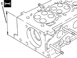
Check that the valves do not show signs of scoring or seizing.
Check that the diameter of the valve stems corresponds to the recommended figures; if not, replace the worn valves.
| Measurement | Value | Validity |
|---|---|---|
| Inlet valve stem diameter (mm) | 5.982 ÷ 6.000 | 1.9 JTD 16V |
| Measurement | Value | Validity |
|---|---|---|
| Exhaust valve stem diameter (mm) | 5.972 ÷ 5.990 | 1.9 JTD 16V |
Check that the length of the valve springs when released is within the recommended values.
| Measurement | Value | Validity |
|---|---|---|
| Valve spring free length (mm) | 43.1 | 1.9 JTD 16V |
Using a torque wrench, check that the valve spring specifications correspond to the recommended figures; if not, replace the worn components.
| Measurement | Value | Validity |
|---|---|---|
| Length of valve springs under a load of 20.47 - 21.84 daN (mm) | 34.0 | 1.9 JTD 16V |
| Measurement | Value | Validity |
|---|---|---|
| Length of valve springs under a load of 44.81 - 47.59 daN (mm) | 24.5 | 1.9 JTD 16V |
Check that the diameter of the camshaft bearings corresponds to the recommended figures; if not, replace the worn camshaft/s.
| Measurement | Value | Validity |
|---|---|---|
| Camshaft first support diameter (mm) | 43.600 ÷ 43.615 | 1.9 JTD 16V |
| Measurement | Value | Validity |
|---|---|---|
| Camshaft second support diameter (mm) | 43.400 ÷ 43.415 | 1.9 JTD 16V |
| Measurement | Value | Validity |
|---|---|---|
| Camshaft third support diameter (mm) | 43.200 ÷ 43.215 | 1.9 JTD 16V |
| Measurement | Value | Validity |
|---|---|---|
| Camshaft fourth support diameter (mm) | 43.000 ÷ 43.015 | 1.9 JTD 16V |
| Measurement | Value | Validity |
|---|---|---|
| Camshaft fifth support diameter (mm) | 30.000 ÷ 30.015 | 1.9 JTD 16V |
Check that the nominal camshaft cam lift corresponds to the recommended figures; if not, replace the worn camshaft/s.
| Measurement | Value | Validity |
|---|---|---|
| Nominal inlet/exhaust cam lift (mm) | 8.0 | 1.9 JTD 16V |
1. Check that the diameter of the camshaft supports corresponds to the recommended figures; if not, replace the cylinder head.
| Measurement | Value | Validity | ||
|---|---|---|---|---|
| Camshaft first support diameter (mm) | 43.646 ÷ 43.671 | 1.9 JTD 16V | ||
| Measurement | Value | Validity | ||
|---|---|---|---|---|
| Camshaft second support diameter (mm) | 43.446 ÷ 43.471 | 1.9 JTD 16V | ||
| Measurement | Value | Validity | ||
|---|---|---|---|---|
| Camshaft third support diameter (mm) | 43.246 ÷ 43.271 | 1.9 JTD 16V | ||
| Measurement | Value | Validity | ||
|---|---|---|---|---|
| Camshaft fourth support diameter (mm) | 43.046 ÷ 43.071 | 1.9 JTD 16V | ||
| Measurement | Value | Validity | ||
|---|---|---|---|---|
| Camshaft fifth support diameter (mm) | 30.045 ÷ 30.070 | 1.9 JTD 16V | ||
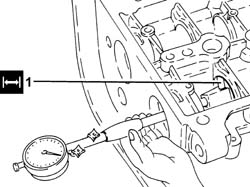
The outer diameter of the valve seats is as follows.
| Measurement | Value | Validity |
|---|---|---|
| Inlet valve seat outer diameter (mm) | 29.600 ÷ 29.611 | 1.9 JTD 16V |
| Measurement | Value | Validity |
|---|---|---|
| Exhaust valve seat outer diameter (mm) | 27.600 ÷ 27.611 | 1.9 JTD 16V |
1. Grind the valve seats to the recommended size.
| Measurement | Value | Validity |
|---|---|---|
| Valve seat band angle in contact with valve | 45° 30’ +/- 1° | 1.9 JTD 16V |
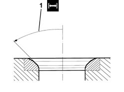
Grind the valve seats using a suitable tool.
LOWER CYLINDER HEAD
Position the lower cylinder head in the vice using the tool.
| Tool | Description | Function | Validity |
|---|---|---|---|
| 1860470000 | Support | Overhaul cylinder head |
Fit the valves in the seats, then support them using the wooden stand and secure it using suitable bolts.
| Tool | Description | Function | Validity |
|---|---|---|---|
| 1860804001 | Stand | Removing/refitting valves | 1.8 1.9 JTD 16V |
1. Place the valve guide oil seal (1a) in position using the tool (1b).
| Tool | Description | Function | Validity |
|---|---|---|---|
| 1870897100 | Extractor/Fitting tool | Extracting/fitting valve guides Valve guide oil seal fitting | 1.9 JTD 16V |
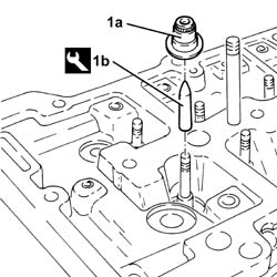
1. Place the shim in position (for exhaust valves only).
2. Fit the valve spring in its seat.
3. Refit the upper valve shim.
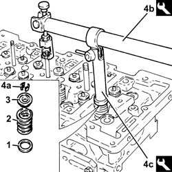
4. Place the cotters (4a) in their housings using the tools (4b) and (4c).
| Tool | Description | Function | Validity |
|---|---|---|---|
| 1860644001 | Lever | Removing/refitting valves | 1.8 1.9 JTD 16V |
| Tool | Description | Function | Validity |
|---|---|---|---|
| 1870890000 | Chamber | Removing/refitting valves | 1.9 JTD 16V |
Carry out the same operations on the other valves.
Remove the wooden stand for supporting the valves from the cylinder head plane.
| Tool | Description | Function | Validity |
|---|---|---|---|
| 1860804001 | Stand | Removing/refitting valves | 1.8 1.9 JTD 16V |
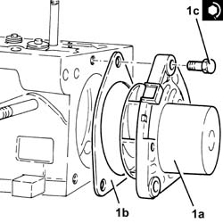
1. Position the water pump (1a), complete with gasket (1b), in its housing and secure it tightening the bolts (1c) to the recommended torque.
| Component | Fastening | dia | Value (daNm) | Validity |
|---|---|---|---|---|
| Water pump | Bolt | M8 | (cylinder head side) 2.3 - 2.8 | 1.9 JTD 8v 1.9 JTD 16v |
1. Place the thermostat (1a) complete with gasket back in its housing and secure it by tightening the bolts (1b) to the recommended torque.
| Component | Fastening | dia | Value (daNm) | Validity |
|---|---|---|---|---|
| Thermostat | Bolt | M8 | (cylinder head side) 2.5 | 1.9 JTD 16v 2.4 JTD 20v |
2. Place the hydraulic tappets in their housings.
- Place the intake manifold gasket in its housing.
- Replace the air conditioning compressor mounting in its housing and secure it by tightening the nuts to the recommended torque.
| Component | Fastening | dia | Value (daNm) | Validity |
|---|---|---|---|---|
| Intake manifold | Nut | M8 | (cylinder head side) 2.3 - 2.8 | 1.9 JTD 16v |
- Connect the degasing pipe to the thermostat and secure with the collar.
- Place the exhaust gas/water heat exchanger for the E.G.R. system back in its housing and secure it by tightening the bolts to the specified torque.
| Component | Fastening | dia | Value (daNm) | Validity |
|---|---|---|---|---|
| Exhaust gas/water heat exchanger for E.G.R. system | Bolt | M8 | (cylinder head side) 2.3 - 2.8 | 1.9 JTD 16v 1.9 JTD 8v 2.4 JTD 20v |
| Component | Fastening | dia | Value (daNm) | Validity |
|---|---|---|---|---|
| Exhaust gas/water heat exchanger for E.G.R. system | Bolt | M8 | (EGR solenoid side) 2.3 - 2.8 | 1.9 JTD 16v 1.9 JTD 8v 2.4 JTD 20v |
- Replace the water pump rigid inlet pipe, complete with gasket, in position and secure it using the bolts, the nut and the collar.
Remove the lower cylinder head from the support tool.
| Tool | Description | Function | Validity |
|---|---|---|---|
| 1860470000 | Support | Overhaul cylinder head |
CYLINDER HEAD EXTENSION
1. Position the cylinder head extension (1a) in a vice using the tool (1b).
| Tool | Description | Function | Validity |
|---|---|---|---|
| 1860470000 | Support | Overhaul cylinder head |
Tighten the engine oil lubrication duct plugs.
Place the camshafts in their housings.
Place the camshaft gears in their housings and secure them without tightening the bolts.
1. Fit the camshaft timing tools.
Check that the tools are correctly fitted in the housings in the camshafts.
| Tool | Description | Function | Validity |
|---|---|---|---|
| 1870896900 | Template | Engine tuning | 1.9 JTD 16V |
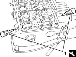
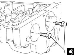
1. Tighten the camshaft gear fixing bolts to the recommended torque.
| Component | Fastening | dia | Value (daNm) | Validity |
|---|---|---|---|---|
| Camshaft gears | Bolt | M12 | (camshaft side) 2.9 - 3.2 + 40° | 1.9 JTD 16v |
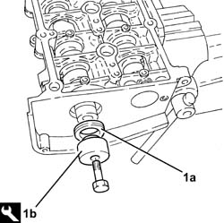
1. Fit the exhaust side camshaft front oil seal (1a) using the tool (1b).
| Tool | Description | Function | Validity |
|---|---|---|---|
| 1870896800 | Fitting tool | Fitting exhaust camshaft oil seal | 1.9 JTD 16V |
Fit the intake side camshaft plug.
Refit the exhaust side camshaft toothed pulley and secure by screwing in the bolt without tightening.
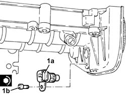
1. Position the cam angle sensor (1a) in its housing and secure it tightening the bolt (1b) to the recommended torque.
| Component | Fastening | dia | Value (daNm) | Validity |
|---|---|---|---|---|
| Cam angle sensor | Bolt (pretreated to be replaced for 1.9 JTD 8v) | M6 | (cylinder head extension side) 0.8 - 1.0 | 1.9 JTD 8V 1.9 JTD 16v 2.4 JTD 20v |
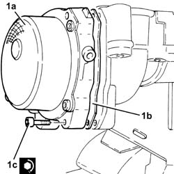
1. Place the vacuum pump (1a), complete with gasket (1b), back in its housing and secure it tightening the bolts (1c) to the recommended torque.
| Component | Fastening | dia | Value (daNm) | Validity |
|---|---|---|---|---|
| Vacuum unit | Bolt (pretreated to be replaced) | M6 | (cylinder head extension side) 0.5 + 50° | 1.9 JTD 16v 2.4 JTD 20v |
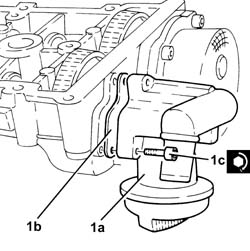
1. Place the engine oil filler fitting (1a), complete with gasket (1b), back in its housing and secure it tightening the bolts (1c) to the recommended torque.
| Component | Fastening | dia | Value (daNm) | Validity |
|---|---|---|---|---|
| Engine oil filler | Bolt | M6 | (cylinder head extension side) 0.8 - 1.0 | 1.9 JTD 16v 2.4 JTD 20v |
Remove the support tool complete with cylinder head extension from the vice and separate them.
Removing
1. Position the cylinder head (1a) in a vice using the tool (1b).
| Tool | Description | Function | Validity |
|---|---|---|---|
| 1860470000 | Support | Overhaul cylinder head |
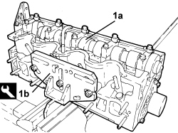
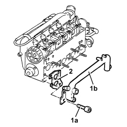
1. Undo the bolts (1a) and remove the water pump inlet pipe (1b).
2. Remove the gasket.
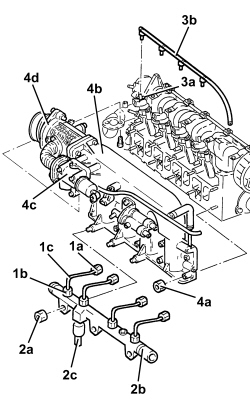
1. Unscrew the connectors (1a) and (1b) and remove the pipes from the fuel manifold to the injectors (1c).
Use new pipes from the fuel manifold to the injectors when refitting.
2. Undo the nuts (2a) and remove the fuel distribution manifold (3b) complete with fuel pressure sensor and pipes (2c).
3. Manually push the clips (3a) and disconnect the pipe from the injectors to the fuel recovery manifold (3b), injector side, and remove it.
- Undo the nuts and disconnect the supply wiring from the heater plugs.
- Disconnect the coolant return pipe to the expansion tank and de-aeration system from the thermostat.
4. Undo the nuts (4a) and remove the air chamber (4b) complete with E.G.R. electrical valve (4c) and throttle body (4d).
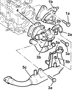
1. Undo the bolts (1a) and remove the vacuum unit (1b) complete with O-ring.
2. Loosen the retaining band (2a) and disconnect the pipe (2b) from the thermostat to the oil heat exchanger, heat exchanger side.
3. Undo the bolts (3a) and remove the thermostat (3b) complete with pipe and sensor.
4. Remove the gasket.
5. Undo the bolt (5a) and the nut (5b) and remove the water/exhaust gas heat exchanger for the E.G.R. system (5c).
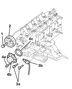
1. Undo the driven toothed pulley bolt.
2. Remove the toothed driven pulley.
3. Undo the bolts (3a) and remove the cam angle sensor (3b).
4. Undo the bolts (4a) and remove the water pump (4b) complete with O-ring (4c).
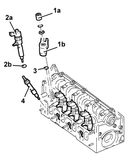
1. Undo the nuts (1a) and remove the brackets (1b) for the injectors.
2. Remove the injectors (2a) complete with gasket (2b).
3. Remove the injector bracket support pads.
4. Remove the heater plugs.
- Check that the camshaft endfloat is within the recommended values using a dial gauge.
| Measurement | Value | Validity |
|---|---|---|
| Camshaft end float | 0.100 - 0.230 mm | 1.9 JTD 8V |
- If the camshaft endfloat is not within the recommended values, replace the worn components when reassembling the cylinder head.
1. Undo the camshaft cap bolts.
2. Remove the camshaft support lubrication pipe.
3. Remove the camshaft caps.
4. Remove the camshaft.
5. Remove the camshaft front oil seal.
6. Remove the cups complete with valve clearance adjustment pads.
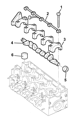
- Remove the cylinder head from the vice.
- Position a suitable wooden stand on the cylinder head plane to support the valves and secure it using bolts.
- Refit the cylinder head in the vice.
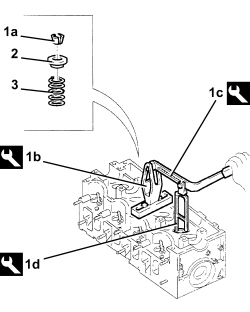
1. Remove the cotters (1a) using the tools (1b), (1c) and (1d).
| Tool | Description | Function | Validity |
|---|---|---|---|
| 1820257000 | Support | Valve support | 1.9 JTD 8V |
| Tool | Description | Function | Validity |
|---|---|---|---|
| 1821058000 | Lever | Valve spring compression lever | 1.9 JTS 2.2 JTS 1.9 JTD 8V |
| Tool | Description | Function | Validity |
|---|---|---|---|
| 1821205000 | Chamber | Removing/ refitting valves | 1.9 JTD 8V |
2. Remove the valve upper shim.
3. Remove the valve spring.
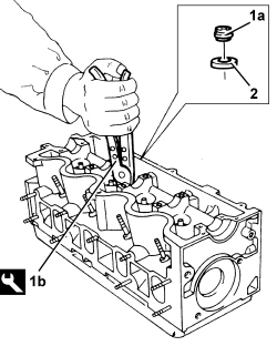
1. Remove the valve guide oil seal (1a) using the tool (1b).
| Tool | Description | Function | Validity |
|---|---|---|---|
| 1870894000 | Extractor | Valve guide oil seal extraction | 1.8 1.9 JTD 8V |
2. Remove the lower shim.
- Carry out the same operations on the other valves.
- Remove the cylinder head from the vice.
- Remove the wooden stand and keep the valves.
- Remove the cylinder head from the support tools.
- Position the cylinder head on the workbench.
1. Thread the special extraction tool (1b) in the valve seat (1a).
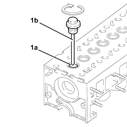
- Turn the cylinder head upsidedown on the workbench.
1. Remove the valve seat (1a) using the extraction tool (1b).
- Carry out the same operations on the other valve seats.
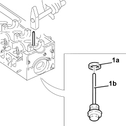
- For the replacement of the valve guides
Op. 1016E14 VALVE GUIDES IN SINGLE CYLINDER HEAD - REPLACE DURING OP. 1016E10
Refitting
- Clean any residues of the old gasket from the lower cylinder head plane.
- Check that the planarity of the lower cylinder head plane corresponds to the recommended values.
| Measurement | Value | Validity | ||
|---|---|---|---|---|
| Cylinder head lower surface flatness | 0.1 mm | 1.9 JTD 8V 2.4 JTD 20V | ||
1. If the planarity of the lower cylinder head plane does not correspond to the recommended figures, regrind it without exceeding the minimum permitted height.
| Measurement | Value | Validity | ||
|---|---|---|---|---|
| Cylinder head lower plane minimum permitted height | 140.85 - 141.15 mm | 1.9 JTD 8V | ||
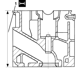
- Check that the valves do not show signs of grooves or seizing.
- Check that the diameter of the valve stems corresponds to the recommended figures; if not, replace the worn valves.
| Measurement | Value | Validity |
|---|---|---|
| Exhaust/inlet valve stem diameter | 7.974 - 7.992 mm | 1.9 JTD 8V |
- Check that the outer diameter of the tappet casings corresponds to the recommended figures; if not, replace the worn components.
| Measurement | Value | Validity |
|---|---|---|
| Tappet rod outer diameter | 36.975 - 36.991 mm | 1.9 JTD 8V |
- Check that the diameter of the hydraulic casing housings corresponds to the recommended figures; if not, replace the cylinder head.
| Measurement | Value | Validity |
|---|---|---|
| Tappet rod housing diameter | 37.010 - 37.030 mm | 1.9 JTD 8V |
- Check that the length of the valve springs released corresponds to the recommended figures; if not, replace the weakened components.
| Measurement | Value | Validity |
|---|---|---|
| Valve spring free length | 53.9 mm | 1.9 JTD 8V |
- Using a torque wrench, check that the spring specifications correspond to the recommended figures; if not, replace the worn components.
| Measurement | Value | Validity |
|---|---|---|
| Length of valve springs under a load of 21.5 - 24.5 daN | 43.12 mm | 1.9 JTD 8V |
| Measurement | Value | Validity |
|---|---|---|
| Length of valve springs under a load of 43.6 - 48.6 daN | 32.34 mm | 1.9 JTD 8V |
- Check that the diameter of the camshaft bearings corresponds to the recommended figures; if not, replace the worn camshaft.
| Measurement | Value | Validity |
|---|---|---|
| Camshaft journal diameter | 26.000 - 26.015 mm | 1.9 JTD 8V |
- Check that the nominal camshaft cam lift corresponds to the recommended figures; if not, replace the worn camshaft.
| Measurement | Value | Validity |
|---|---|---|
| Nominal inlet cam lift | 8.5 mm | 1.9 JTD 8V |
| Measurement | Value | Validity |
|---|---|---|
| Nominal exhaust cam lift | 9.0 mm | 1.9 JTD 8V |
1. Fit the camshaft caps (1a) on the cylinder head and tighten the bolts (1b) to the recommended torque.
| Component | Fastening | dia | Value (daNm) | Validity |
|---|---|---|---|---|
| Camshaft caps | Bolt | M7 | (cylinder head side) 1.3 - 1.6 | 1.9 JTD 8V |
2. Check that the diameter of the camshaft supports corresponds to the recommended figures; if not, replace the cylinder head.
| Measurement | Value | Validity |
|---|---|---|
| Diameter of camshaft mounts | 26.045 - 26.070 mm | 1.9 JTD 8V |
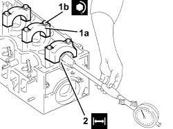
- Check that the outer diameter of the valve seats to be fitted corresponds to the recommended figures.
| Measurement | Value | Validity |
|---|---|---|
| Inlet valve seat outer diameter | 36.039 - 36.064 mm | 1.9 JTD 8V |
| Measurement | Value | Validity |
|---|---|---|
| Exhaust valve seat outer diameter | 35.039 - 35.064 mm | 1.9 JTD 8V |
1. Fit the valve seats (1a) using a suitable tool (1b).
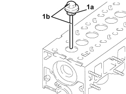
1. Grind the valve seats to the recommended size.
| Measurement | Value | Validity |
|---|---|---|
| Valve seat band angle in contact with valve | 45° +/- 20’ | 1.9 JTD 8V |
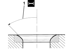
- Grind the valve seats using a suitable tool.
- Temporarily fit the valves.
1. Check that the valve recess in relation to the cylinder head plane (1a) corresponds to the recommended figures using the tool (1b) fitted with a dial gauge.
| Measurement | Value | Validity |
|---|---|---|
| Valve recess in relation to cylinder head plane | 0.1 - 0.5 mm | 1.9 JTD 8V |
| Tool | Description | Function | Validity |
|---|---|---|---|
| 1820253000 | Dial gauge support | Measure the piston projection/valve recess in relation to the cylinder head plane | 1.9 JTD 8V 2.4 JTD 20V |
- If the valve recess in relation to the cylinder head plane does not correspond to the recommended figures, regrind the valve seats once again.
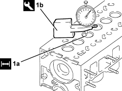
- Place a suitable wooden bench between the support tools and the cylinder head to support the valves.
- Fit the cylinder head, complete with valves, on the support tools and secure it using the nuts.
- Fit the lower shim.
1. Fit the valve guide oil seals (1a) using the tools (1b) and (1c).
| Tool | Description | Function | Validity |
|---|---|---|---|
| 1860814001 | Shrink disk | Fit valve oil seals | 1.9 JTS 2.2 JTS 1.9 JTD 8V |
| Tool | Description | Function | Validity |
|---|---|---|---|
| 1821178000 | Fitting tool | Valve guide oil seal fitting | 1.9 JTD 8V |
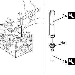
- Fit the valve spring.
- Fit the valve upper shim.
1. Fit the cotters (1a) using the tools (1b), (1c) and (1d).
| Tool | Description | Function | Validity |
|---|---|---|---|
| 1820257000 | Support | Valve support | 1.9 JTD 8V |
| Tool | Description | Function | Validity |
|---|---|---|---|
| 1821058000 | Lever | Valve spring compression lever | 1.9 JTS 2.2 JTS 1.9 JTD 8V |
| Tool | Description | Function | Validity |
|---|---|---|---|
| 1821205000 | Chamber | Removing/ refitting valves | 1.9 JTD 8V |
- Carry out the same operations on the other valves.
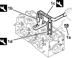
- Remove the cylinder head from the vice.
- Remove the wooden stand supporting the valves.
- Refit the cylinder head in the vice.
- Fit the cups complete with valve clearance adjustment pads.
- Fit the camshaft.
1. Fit the camshaft caps.
Apply LOCTITE to the contact surfaces with the head for the 1st and 5th camshaft caps.
- Fit the camshaft bearing lubrication pipe.
2. Tighten the camshaft cap bolts to the recommended torque.
| Component | Fastening | dia | Value (daNm) | Validity |
|---|---|---|---|---|
| Camshaft caps | Bolt | M7 | (cylinder head side) 1.3 - 1.6 | 1.9 JTD 8V |
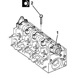
1. Fit the camshaft front oil seal (1a) using the tool (1b).
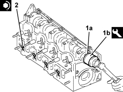
2. Fit the spark plugs and tighten them to the recommended torque.
| Component | Fastening | dia | Value (daNm) | Validity |
|---|---|---|---|---|
| Heater plug | M12 | 1.3 ÷ 1.6 | 1.9 Multijet |
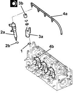
1. Fit the injector bracket support pads.
2. Fit the injectors (2a) complete with gasket (2b).
3. Fit the injector brackets (3a) and tighten the nuts (3b) to the recommended torque.
| Component | Fastening | dia | Value (daNm) | Validity |
|---|---|---|---|---|
| Injector brackets | Nut | M8 | 2.7 ÷ 3.3 | 1.9 JTD 8V |
4. Position the connectors for the pipe from the injectors to the fuel recovery manifold (4a) in the corresponding injector seats and insert them fully until the clip (4b) can be heard to click.
- Fit the water pump, complete with a new O-Ring and tighten the bolts to the recommended torque.
| Component | Fastening | dia | Value (daNm) | Validity |
|---|---|---|---|---|
| Water pump | Bolt | M8 | (cylinder head side) 2.3 - 2.8 | 1.9 JTD 8V 1.9 JTD 16V 2.4 JTD 20V |
- Fit the cam angle sensor and tighten the bolts.
- Fit the driven toothed pulley and tighten the bolt to the recommended torque.
| Component | Fastening | dia | Value (daNm) | Validity |
|---|---|---|---|---|
| Driven toothed pulley | Bolt | M12 | (camshaft side) 2.9 - 3.2 + 40° | 1.9 JTD 8V 1.9 JTD 16V 2.4 JTD 20V |
- Check that the valve clearance, with the valves closed, corresponds to the recommended figures; if not, replace the valve clearance adjustment pads following the instructions given below.
| Measurement | Value | Validity |
|---|---|---|
| Inlet valves clearance in closed position | 0.25 - 0.35 mm | 1.9 JTD 8V |
| Measurement | Value | Validity |
|---|---|---|
| Exhaust valves clearance in closed position | 0.30 - 0.40 mm | 1.9 JTD 8V |
1. Lower the tappets in question using the tool.
| Tool | Description | Function | Validity |
|---|---|---|---|
| 1820262000 | Lever | Lower tappets | 1.9 JTD 8V |
2. Fit the tool.
| Tool | Description | Function | Validity |
|---|---|---|---|
| 1860724001 | Lever | Keep valve tappets lowered | 1.9 JTD 8V |
- Remove the tool.
| Tool | Description | Function | Validity |
|---|---|---|---|
| 1820262000 | Lever | Lower tappets | 1.9 JTD 8V |
- Extract the valve clearanance adjustment plate and replace it with a one of a suitable thickness.
- Remove the tool.
| Tool | Description | Function | Validity |
|---|---|---|---|
| 1860724001 | Lever | Keep valve tappets lowered | 1.9 JTD 8V |
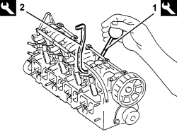
- Refit the water/exhaust gas heat exchanger for the E.G.R. system and secure it using the bolt and the nut.
- Fit the thermostat complete with gasket, pipes and sensor then tighten the bolts to the recommended torque.
| Component | Fastening | dia | Value (daNm) | Validity |
|---|---|---|---|---|
| Thermostat | Bolt | M8 | (cylinder head side) 2.3 - 2.8 | 1.9 JTD 8V |
- Connect the pipe from the thermostat to the heat exchanger and tighten the band.
- Place the vacuum unit in its housing with the O-ring and secure it by tightening the bolts to the recommended torque.
| Component | Fastening | dia | Value (daNm) | Validity |
|---|---|---|---|---|
| Vacuum unit | Bolt | M8 | (cylinder head side) 2.7 - 3.3 | 1.9 JTD 8V |
- Fit the air chamber assembly and tighten the nuts.
- Connect the coolant return pipe to the expansion tank and de-aeration system to the thermostat.
- Position the heater plugs supply wiring and secure it using the nuts.
- Place the pipe from the injectors to the fuel recovery manifold back in its housing and connect it to the injectors and push home until the clips click into place.
- Fit the fuel distribution manifold complete with fuel pressure sensor and tighten the nuts.
- Place the new pipes from the fuel manifold ot the injectors in their housings.
- Tighten the connectors for the pipes from the fuel manifold to the injector side injectors to the recommended torque.
| Component | Fastening | dia | Value (daNm) | Validity |
|---|---|---|---|---|
| Pipes from fuel manifold to injectors | Connector | M12 | (injector side) 2.2 - 2.4 | 1.9 JTD 8V |
- Tighten the connectors for the pipes from the fuel manifold to the manifold side injectors to the recommended torque.
| Component | Fastening | dia | Value (daNm) | Validity |
|---|---|---|---|---|
| Pipes from fuel manifold to injectors | Connector | M14 | (fuel manifold side) 2.2 - 2.4 | 1.9 JTD 8V |
- Fit the water pump rigid inlet pipe complete with gasket and tighten the bolts.
- Remove the support tool.
Removing
1. Fit support tool (1a) on cylinder head (1b) and place it in the vice.
| Tool | Description | Function | Validity |
|---|---|---|---|
| 1860470000 | Support | Overhaul cylinder head |
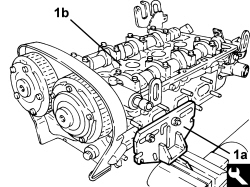
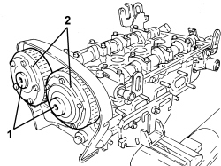
1. Undo the protective plugs.
2. Undo the bolts and remove the pullies.
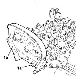
1. Undo bolts (1a) and remove timing belt inner guard (1b).
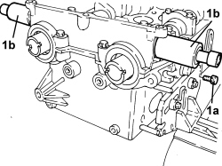
1. Undo bolts (1a) and remove phase transformer solenoid valves (1b).
- Undo the bolts and remove the engine lifting brackets.
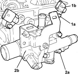
1. Undo bolts (1a) and remove timing sensors (1b).
2. Undo bolts (2a) and remove thermostat unit (2b).
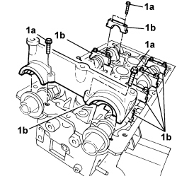
1. Undo bolts (1a) and remove camshaft caps (1b).
The camshaft caps are numbered from 2 to 5, inlet side and from 6 to 9, exhaust side. The front cap, which is the same for both camshafts, is number 1.
The bolts securing the camshaft caps should be loosened in a spiral sequence, starting from the caps on the outside, in the following order: 5 - 2 - 4 - 3.
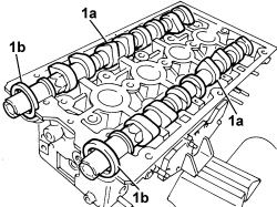
Mark the fitting position of the camshafts.
1. Remove camshafts (1a) and oil seals (1b).
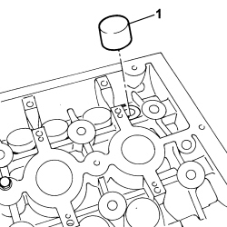
1. Remove the tappet cups.
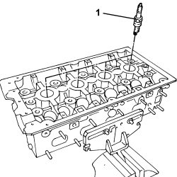
1. Unscrew the spark plugs and remove them.
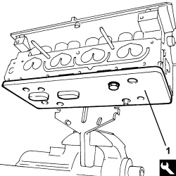
1. Fit the tool in the lower part of the cylinder head.
| Tool | Description | Function | Validity |
|---|---|---|---|
| 1860804001 | Stand | Removing/refitting valves | 1.8 1.9 JTD 16V |
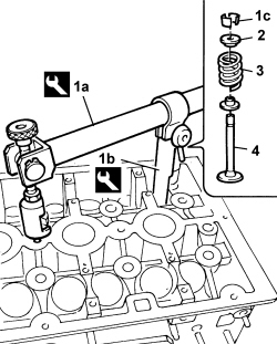
1. Fit cotters (1c) using tools (1a) and (1b).
| Tool | Description | Function | Validity |
|---|---|---|---|
| 1860644001 | Lever | Removing/refitting valves | 1.8 1.9 JTD 16V |
| Tool | Description | Function | Validity |
|---|---|---|---|
| 1870881000 | Chamber | Removing/refitting valves | 1.8 |
2. Remove the shim.
3. Remove the valve spring.
- Carry out the same operations for removing the remaining valves.
- Remove the valve support fitted previously.
4. Remove the valves.
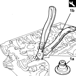
1. Remove valve guide oil seal (1a) using tool (1b).
| Tool | Description | Function | Validity |
|---|---|---|---|
| 1870894000 | Extractor | Valve guide oil seal extraction | 1.8 1.9 JTD 8V |
- Carry out the same operations for removing the remaining oil seals.
- Remove the cylinder head from the support tool.
Op. 1016E14 VALVE GUIDES IN SINGLE CYLINDER HEAD - REPLACE DURING OP. 1016E10
Refitting
- Thoroughly clean the matching surfaces between the cylinder head and the engine block.
- Check that the planarity of the lower cylinder head plane is within the recommended values. If this is not the case, replace the cylinder head (the cylinder head lower plane cannot be reground).
| Measurement | Value | Validity | ||
|---|---|---|---|---|
| Cylinder head lower surface flatness | 0.05 mm | 1.8 | ||
- Fit the cylinder head support tool and place the assembly in a vice.
- Check that the valves do not show signs of grooves or seizing.
1. Check that the width of the valve bore in the cylinder head is within the recommended values.
| Measurement | Value | Validity |
|---|---|---|
| Inlet valve seat width (mm) | 1.0 ÷ 1.4 | 1.8 |
| Measurement | Value | Validity |
|---|---|---|
| Exhaust valve seat width (mm) | 1.8 |
2. Check that the angle of the valve bore in the cylinder head is within the recommended values.
| Measurement | Value | Validity |
|---|---|---|
| Valve seat angle | 90° 30’ | 1.8 |
- If the values are not within the recommended limits, replace the cylinder head.
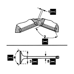
3. Check that the diameter of the valve head corresponds to the recommended figures.
| Measurement | Value | Validity |
|---|---|---|
| Inlet valve head diameter (mm) | 30.7 ÷ 30.8 | 1.8 |
| Measurement | Value | Validity |
|---|---|---|
| Exhaust valve head diameter (mm) | 27.1 ÷ 27.2 | 1.8 |
4. Check that the angle of the valve head is within the recommended values.
| Measurement | Value | Validity |
|---|---|---|
| Valve head angle | 90° 40’ | 1.8 |
5. Check that the diameter of the valve stem corresponds to the recommended figures.
| Measurement | Value | Validity |
|---|---|---|
| Inlet valve stem diameter (mm) | 4.955 ÷ 4.970 | 1.8 |
| Measurement | Value | Validity |
|---|---|---|
| Exhaust valve stem diameter (mm) | 4.935 ÷ 4.950 | 1.8 |
| Measurement | Value | Validity |
|---|---|---|
| Valve stem diameter oversizes (mm) | 0.075/0.150 | 1.8 |
- If the values are not within the recommended limits, replace the valves.
Op. 1016E14 VALVE GUIDES IN SINGLE CYLINDER HEAD - REPLACE DURING OP. 1016E10
- Place the valves in their seats and support them using the support tool.
| Tool | Description | Function | Validity |
|---|---|---|---|
| 1860804001 | Stand | Removing/refitting valves | 1.8 1.9 JTD 16V |
- Fit the valve guide oil seal using the tool.
| Tool | Description | Function | Validity |
|---|---|---|---|
| 1870894000 | Extractor | Valve guide oil seal extraction | 1.8 1.9 JTD 8V |
- Fit the springs and the shim.
- Position the lever fitted with an adaptor, compress the valve spring and fit the cotters.
| Tool | Description | Function | Validity |
|---|---|---|---|
| 1860644001 | Lever | Removing/refitting valves | 1.8 1.9 JTD 16V |
| Tool | Description | Function | Validity |
|---|---|---|---|
| 1870881000 | Chamber | Removing/refitting valves | 1.8 |
- Proceed in a similar way and fit the remaining oil seals, springs, shims and cotters.
- Undo the bolts and remove the valve support tool.
| Tool | Description | Function | Validity |
|---|---|---|---|
| 1860804001 | Stand | Removing/refitting valves | 1.8 1.9 JTD 16V |
- Fit the mechanical tappet cups.
- Fit the inlet and exhaust side camshafts, following the position marked during the dismantling.
- Fit two new oil seals on the camshafts, having lubricated them with engine oil.
- Apply a bead of silicon sealant to the matching surfaces of the camshaft front cap.
- Place the camshaft front cap in position using the two centering bushes.
- Place the camshaft caps in position, following the progressive numbers indicated during the removal.
- Tighten to the recommended torque the bolts fixing the camshaft caps, following the spiral sequence from the inside towards the outside.
| Component | Fastening | dia | Value (daNm) | Validity |
|---|---|---|---|---|
| Camshaft caps | Bolt | 0.8 | 1.8 |
1. Use a feeler gauge to check that the valve clearance is within the specified limits with the valves closed.
| Measurement | Value | Validity |
|---|---|---|
| Inlet valve clearance in closed position (mm) | 0.21 ÷ 0.29 | 1.8 |
| Measurement | Value | Validity |
|---|---|---|
| Exhaust valve clearance in closed position (mm) | 0.27 ÷ 0.35 | 1.8 |
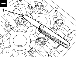
- If the tappet clearance is not within the recommended tolerance, remove the camshaft involved and replace the cups, selecting the size according to the required clearance.
The tappet cups are graded according to size and therefore the Spare Parts list should be consulted for selecting the new cup to be fitted. The code is on the cup crown.
- After fitting the new cups, repeat the procedure for checking the tappet clearance.
- Fit the timing belt inner guard and secure it using the bolts.
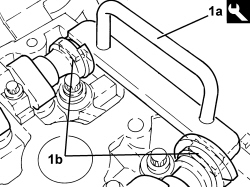
1. Fit tool (1a) in special splining on camshafts (1b).
| Tool | Description | Function | Validity |
|---|---|---|---|
| 2000012000 | Template | Camshaft timing | 1.8 |
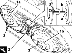
1. Place toothed driven pullies (1a) and (1b) in position.
2. Fit the tool on the toothed driven pullies.
| Tool | Description | Function | Validity |
|---|---|---|---|
| 2000012100 | Template | Camshaft timing | 1.8 |
Fit the inlet side template first and then the exhaust side one.
When the templates are fitted, check that:
- the reference (a) on the exhaust-side pulley is aligned with the reference (b) on the corresponding timing template;
- the pin (c) on the intake-side pulley is in the position illustrated in the diagram in relation to the reference (d) on the corresponding timing template.
- Tighten the bolts fixing the pullies to the recommended torque.
| Component | Fastening | dia | Value (daNm) | Validity |
|---|---|---|---|---|
| Variable valve timing actuator | Bolt (to be replaced) | 6.5 + 120° + 15° | 1.8 |
3. Tighten the sealing plugs with new O-rings.
- Remove the templates used for timing.
- Place the thermostat unit in its housing complete with a new O-ring and tighten the fixing bolts.
- Place the inlet and exhaust side timing sensors in position and secure them using the bolts.
| Component | Fastening | dia | Value (daNm) | Validity |
|---|---|---|---|---|
| Timing sensor | Bolt | M6 | 0.6 ÷ 0.8 | 1.8 |
- Place the inlet and exhaust side phase transformer solenoid valves in position and secure them using the bolt.
- Fit the spark plugs and tighten them to the recommended torque.
| Component | Fastening | dia | Value (daNm) | Validity |
|---|---|---|---|---|
| Spark plugs | 2.5 | 1.8 |
- Place the engine lifting brackets in their housings and secure them using the bolts.
- Undo the fixing nuts and remove the cylinder head from the support tool.
- Remove the support tool from the vice.
Removing
CAMSHAFT HOUSING
1. Position the camshaft housing (1a) in a vice using the tool (1b).
| Tool | Description | Function | Validity |
|---|---|---|---|
| 1860470000 | Support | Overhaul cylinder head |
1. Undo the bolts (1a) and remove the engine oil filler (1b).
2. Remove the gasket.
1. Undo the bolts (1a) and remove the vacuum unit (1b).
2. Remove the gasket.
1. Undo the bolt (1a) and remove the cam angle sensor (1b).
1. Remove plugs (1a) and fit camshaft timing tools (1b) on the camshaft housing.
Check that the tools are correctly fitted in the housings in the camshafts.
| Tool | Description | Function | Validity |
|---|---|---|---|
| 1870896900 | Template | Engine tuning | 1.9 JTD 16V 2.4 JTD 20V |
1. Undo the bolts fixing the camshaft gears.
1. Undo the bolt (1a) and remove the exhaust side camshaft toothed drive pulley (1b).
Remove the camshaft timing tools from the cylinder head extension.
| Tool | Description | Function | Validity |
|---|---|---|---|
| 1870896900 | Template | Engine tuning | 1.9 JTD 16V 2.4 JTD 20V |
1. Wtihdraw the camshafts (1a), as far as necessary and remove the camshaft gears (1b).
1. Using a suitable drift, extract the inlet side camshaft (1a) and plug (1b).
2. Using a suitable drift, extract the exhaust side camshaft (2a) and oil seal (2b).
1. Undo and remove the engine oil lubrication duct plugs.
LOWER CYLINDER HEAD
1. Position the cylinder head (1a) in a vice using the tool (1b).
| Tool | Description | Function | Validity |
|---|---|---|---|
| 1860470000 | Support | Overhaul cylinder head |
1. Loosen the band (1a), undo the bolts (1b), then remove the rigid fluid inlet pipe to the water pump assembly (1c).
- Remove the gasket.
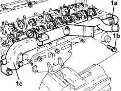
- Loosen the band and disconnect the degassing pipe from the thermostat.
1. Loosen the collar and disconnect the E.G.r. exhaust gas pipe, heat exchanger side.
2. Undo the nuts (2a) and remove the air chamber (2b) complete with E.G.R. valve (2c) and throttle body (2d).
- Remove the gasket.
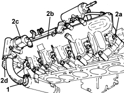
- Remove the hydraulic tappets.
1. Loosen the band (1a), undo the bolts (1a) and remove the thermostat (1b) complete with O-ring.
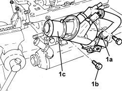
1. Undo the bolts (1a) and remove the water/exhaust gas heat exchanger for the E.G.R. system (1b).
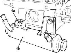
1. Undo the bolts (1a) and remove the water pump (1b).
2. Remove the gasket.
1. Fit a wooden stand on the cylinder head plane to support the valves and secure it using bolts.
| Tool | Description | Function | Validity |
|---|---|---|---|
| 1860804001 | Stand | Removing/ refitting valves | 1.8 1.9 JTD 16V 2.4 JTD 20V |
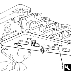
1. Fit the cotters (1a) using the tools (1b) and (1c).
| Tool | Description | Function | Validity |
|---|---|---|---|
| 1860644001 | Lever | Removing/ refitting valves | 1.8 1.9 JTD 16V 2.4 JTD 20V |
| Tool | Description | Function | Validity |
|---|---|---|---|
| 1870890000 | Chamber | Removing/ refitting valves | 1.9 JTD 16V 2.4 JTD 20V |
2. Remove the valve upper shim.
3. Remove the valve spring.
4. Remove the shim (for exhaust valves only).
5. Remove the valve guide oil seal with integrated lower valve shim.
Carry out the same operations on the other valves.
Remove the wooden stand and recover the valves.
| Tool | Description | Function | Validity |
|---|---|---|---|
| 1860804001 | Stand | Removing/ refitting valves | 1.8 1.9 JTD 16V 2.4 JTD 20V |
Remove the lower cylinder head from the support tool.
| Tool | Description | Function | Validity |
|---|---|---|---|
| 1860470000 | Support | Overhaul cylinder head |
Replace the valve guide
Op. 1016E14 VALVE GUIDES IN SINGLE CYLINDER HEAD - REPLACE DURING OP. 1016E10
Refitting
LOWER CYLINDER HEAD
Clean any residues of the old gasket from the lower cylinder head plane.
Check that the flatness of the lower cylinder head plane corresponds to the recommended values.
| Measurement | Value | Validity | ||
|---|---|---|---|---|
| Cylinder head lower surface flatness | 0.1 mm | 1.9 JTD 8V 2.4 JTD 20V | ||
1. If the planarity of the lower cylinder head plane does not correspond to the recommended figures, regrind it without exceeding the minimum permitted height.
| Measurement | Value | Validity | ||
|---|---|---|---|---|
| Cylinder head lower plane minimum permitted height | 107.0 ± 0.05 mm | 2.4 JTD 20V | ||
Check that the valves do not show signs of scoring or seizing.
Check that the diameter of the valve stems corresponds to the recommended figures; if not, replace the worn valves.
| Measurement | Value | Validity |
|---|---|---|
| Inlet valve stem diameter | 5.982 - 6.000 mm | 1.9 JTD 16V 2.4 JTD 20V |
| Measurement | Value | Validity |
|---|---|---|
| Exhaust valve stem diameter | 5.972 ÷ 5.990 | 1.9 JTD 16V 2.4 JTD 20V |
Check that the length of the valve springs when released is within the recommended values.
| Measurement | Value | Validity |
|---|---|---|
| Valve spring free length | 43.1 mm | 1.9 JTD 16V 2.4 JTD 20V |
Using a torque wrench, check that the valve spring specifications correspond to the recommended figures; if not, replace the worn components.
| Measurement | Value | Validity |
|---|---|---|
| Length of valve springs under a load of 20.47 - 21.84 daN | 34.0 mm | 1.9 JTD 16V 2.4 JTD 20V |
| Measurement | Value | Validity |
|---|---|---|
| Length of valve springs under a load of 44.81 - 47.59 daN | 24.5 mm | 1.9 JTD 16V 2.4 JTD 20V |
Check that the diameter of the camshaft bearings corresponds to the recommended figures; if not, replace the worn camshaft/s.
| Measurement | Value | Validity |
|---|---|---|
| Diameter of inlet and exhaust shaft first bearing | 43.800 - 43.815 mm | 2.4 JTD 20V |
| Measurement | Value | Validity |
|---|---|---|
| Diameter of inlet and exhaust shaft second bearing | 43.600 - 43.615 mm | 2.4 JTD 20V |
| Measurement | Value | Validity |
|---|---|---|
| Diameter of inlet and exhaust shaft third bearing | 43.400 - 43.415 mm | 2.4 JTD 20V |
| Measurement | Value | Validity |
|---|---|---|
| Diameter of inlet and exhaust shaft fourth bearing | 43.200 - 43.215 mm | 2.4 JTD 20V |
| Measurement | Value | Validity |
|---|---|---|
| Diameter of inlet and exhaust shaft fifth bearing | 43.000 - 43.015 mm | 2.4 JTD 20V |
| Measurement | Value | Validity |
|---|---|---|
| Diameter of inlet and exhaust shaft sixth bearing | 30.000 - 30.015 mm | 2.4 JTD 20V |
Check that the nominal camshaft cam lift corresponds to the recommended figures; if not, replace the worn camshaft/s.
| Measurement | Value | Validity |
|---|---|---|
| Nominal inlet/exhaust cam lift | 8.0 mm | 1.9 JTD 16V 2.4 JTD 20V |
1. Check that the diameter of the camshaft supports corresponds to the recommended figures; if not, replace the cylinder head.
| Measurement | Value | Validity |
|---|---|---|
| Diameter of inlet and exhaust shaft first bearing | 43.846 - 43.871 mm | 2.4 JTD 20V |
| Measurement | Value | Validity |
|---|---|---|
| Diameter of inlet and exhaust shaft second support | 43.646 - 43.671 mm | 2.4 JTD 20V |
| Measurement | Value | Validity |
|---|---|---|
| Diameter of inlet and exhaust shaft third support | 43.446 - 43.471 mm | 2.4 JTD 20V |
| Measurement | Value | Validity |
|---|---|---|
| Diameter of inlet and exhaust shaft fourth support | 43.246 - 43.271 mm | 2.4 JTD 20V |
| Measurement | Value | Validity |
|---|---|---|
| Diameter of inlet and exhaust shaft fifth support | 43.046 - 43.071 mm | 2.4 JTD 20V |
| Measurement | Value | Validity |
|---|---|---|
| Diameter of inlet and exhaust shaft sixth support | 30.045 - 30.070 mm | 2.4 JTD 20V |
The outer diameter of the valve seats is as follows.
| Measurement | Value | Validity |
|---|---|---|
| Inlet valve seat outer diameter | 29.600 - 29.611 mm | 1.9 JTD 16V 2.4 JTD 20V |
| Measurement | Value | Validity |
|---|---|---|
| Exhaust valve seat outer diameter | 27.600 - 27.611 mm | 1.9 JTD 16V 2.4 JTD 20V |
1. Grind the valve seats to the recommended size.
| Measurement | Value | Validity |
|---|---|---|
| Valve seat band angle in contact with valve | 45° +/- 1’ | 1.9 JTD 16V 2.4 JTD 20V |
Grind the valve seats using a suitable tool.
Position the lower cylinder head in the vice using the tool.
| Tool | Description | Function | Validity |
|---|---|---|---|
| 1860470000 | Support | Overhaul cylinder head |
Fit the valves in the seats, then support them using the wooden stand and secure it using suitable bolts.
| Tool | Description | Function | Validity |
|---|---|---|---|
| 1860804001 | Stand | Removing/ refitting valves | 1.8 1.9 JTD 16V 2.4 JTD 20V |
1. Place the valve guide oil seal (1a) in position using the tool (1b).
| Tool | Description | Function | Validity |
|---|---|---|---|
| 1870897100 | Extractor/ Fitting tool | Extracting/fitting valve guides Valve guide oil seal fitting | 1.9 JTD 16V 2.4 JTD 20V |
1. Place the shim in position (for exhaust valves only).
2. Fit the valve spring in its seat.
3. Refit the upper valve shim.
4. Place the cotters (4a) in their housings using the tools (4b) and (4c).
| Tool | Description | Function | Validity |
|---|---|---|---|
| 1860644001 | Lever | Removing/ refitting valves | 1.8 1.9 JTD 16V 2.4 JTD 20V |
| Tool | Description | Function | Validity |
|---|---|---|---|
| 1870890000 | Chamber | Removing/ refitting valves | 1.9 JTD 16V 2.4 JTD 20V |
Carry out the same operations on the other valves.
Remove the wooden stand for supporting the valves from the cylinder head plane.
| Tool | Description | Function | Validity |
|---|---|---|---|
| 1860804001 | Stand | Removing/ refitting valves | 1.8 1.9 JTD 16V 2.4 JTD 20V |
- Refit the water pump, complete with gasket, in its housing and secure it tightening the bolts to the recommended torque.
| Component | Fastening | dia | Value (daNm) | Validity |
|---|---|---|---|---|
| Water pump | Bolt | M8 | (cylinder head side) 2.3 - 2.8 | 1.9 JTD 8V 1.9 JTD 16V 2.4 JTD 20V |
- Place the engine oil heat exchanger for the E.G.R system in its housing and secure it to the cylinder head tightening the bolts to the recommended torque.
| Component | Fastening | dia | Value (daNm) | Validity |
|---|---|---|---|---|
| Exhaust gas/water heat exchanger for E.G.R. system | Bolt | M8 | (cylinder head side) 2.3 - 2.8 | 1.9 JTD 8V 1.9 JTD 16V 2.4 JTD 20V |
- Place the thermostat in its housing with the new O-ring and secure it to the cylinder head by tightening the bolts to the recommended torque.
| Component | Fastening | dia | Value (daNm) | Validity |
|---|---|---|---|---|
| Thermostat | Bolt | M8 | (cylinder head side) 2.5 | 1.9 JTD 16V 2.4 JTD 20V |
- Place the hydraulic tappets in their housings.
- Connect the water return pipe from the E.G.R. heat exchanger and secure it using the band.
- Place the intake manifold gasket in its housing.
- Replace the air chamber complete with E.G.R. valve in its housing and secure it by tightening the nuts to the recommended torque.
| Component | Fastening | dia | Value (daNm) | Validity |
|---|---|---|---|---|
| Intake manifold | Nut | M8 | (cylinder head side) 2.3 - 2.8 | 1.9 JTD 16V 2.4 JTD 20V |
- Connect the degassing pipe to the thermostat and secure with the band.
- Place the water pump rigid return pipe, complete with gasket, in position and tighten the bolts.
- Connect the the flexible water return pipe from the E.G.R. heat exchanger to the water pump rigid return pipe and secure it using the band.
Remove the lower cylinder head from the support tool.
| Tool | Description | Function | Validity |
|---|---|---|---|
| 1860470000 | Support | Overhaul cylinder head |
CAMSHAFT HOUSING
- Position the camshaft housing in the vice using the tool.
| Tool | Description | Function | Validity |
|---|---|---|---|
| 1860470000 | Support | Overhaul cylinder head |
Tighten the engine oil lubrication duct plugs.
Place the camshafts in their housings.
Place the camshaft gears in their housings and secure them without tightening the bolts.
1. Fit the camshaft timing tools.
Check that the tools are correctly fitted in the housings in the camshafts.
| Tool | Description | Function | Validity |
|---|---|---|---|
| 1870896900 | Template | Engine tuning | 1.9 JTD 16V 2.4 JTD 20V |
1. Tighten the camshaft gear fixing bolts to the recommended torque.
| Component | Fastening | dia | Value (daNm) | Validity |
|---|---|---|---|---|
| Camshaft gears | Bolt | M12 | (camshaft side) 2.9 - 3.2 + 40° | 1.9 JTD 16V 2.4 JTD 20V |
1. Fit the exhaust side camshaft front oil seal (1a) using the tool (1b).
| Tool | Description | Function | Validity |
|---|---|---|---|
| 1870896800 | Fitting tool | Fitting exhaust camshaft oil seal | 1.9 JTD 16V 2.4 JTD 20V |
Fit the intake side camshaft plug.
Refit the exhaust side camshaft toothed pulley and secure by screwing in the bolt without tightening.
1. Position the cam angle sensor (1a) in its housing and secure it tightening the bolt (1b) to the recommended torque.
| Component | Fastening | dia | Value (daNm) | Validity |
|---|---|---|---|---|
| Cam angle sensor | Bolt | M6 | (cylinder head extension side) 0.8 - 1.0 | 1.9 JTD 16V 2.4 JTD 20V |
1. Place the vacuum pump (1a), complete with gasket (1b), back in its housing and secure it tightening the bolts (1c) to the recommended torque.
| Component | Fastening | dia | Value (daNm) | Validity |
|---|---|---|---|---|
| Vacuum unit | Bolt (pretreated to be replaced) | M6 | (cylinder head extension side) 0.5 + 50° | 1.9 JTD 16V 2.4 JTD 20V |
1. Place the engine oil filler fitting (1a), complete with gasket (1b), back in its housing and secure it tightening the bolts (1c) to the recommended torque.
| Component | Fastening | dia | Value (daNm) | Validity |
|---|---|---|---|---|
| Engine oil filler | Bolt | M6 | (cylinder head extension side) 0.8 - 1.0 | 1.9 JTD 16V 2.4 JTD 20V |
Remove the support tool complete with cylinder head extension from the vice and separate them.
Parts & tools for this job Staging For 2005 Alfa Romeo 159
- PARTEngine gasket setSearch: Alfa Romeo 159 2005 engine gasket set
- TOOLTorque wrenchSearch: 3/8 inch torque wrench
- TOOLFeeler gauge setSearch: feeler gauge set
Links open Amazon search results in a new tab. As an Amazon Associate I earn from qualifying purchases.