
Introduction - cylinder head(s)
- Make
- Alfa Romeo
- Model
- 159 Factory Service Manual
- Year
- 2005–2011
- Section
- Cylinder head/s › Introduction - cylinder head(s)
INTRODUCTION - CYLINDER HEAD(S)
The cylinder head is one-piece in aluminium alloy and silicone.
The four valves per cylinder are fitted in guides arranged in a V and driven by two camshafts via hydraulic tappets.
The arrangement of the spaces allows the combustion chamber to house:
- the four valve heads
- the spark plug opening angled toward the exhaust duct
- the injector opening;
with the advantage of improving the thermal efficiency of the engine and reducing harmful exhaust emissions.
The valve guides are an interference fit in the cylinder head seats.
A special reamer is used to produce the correct inner diameter after fitting.
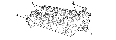
1. Fuel pressure pump
2. Timing sensors
3. Head coolant inlet connection
4. Camshafts
CONSTRUCTION SPECIFICATIONS
The nylon tappet cover incorporates the oil vapour separator
1080D IMPIANTO RICIRCOLO VAPORI/GAS DEL BASAMENTO
, it closes the top of the cylinder head and a special gasket ensures the seal.
Technical specifications
The cylinder heads are the monolith type made from aluminium alloy and support and house the timing system components, the intake and exhaust manifolds, the housings for the spark plugs, the housings for the injectors and determine the shape of the combustion chamber.
The intake manifold and combustion chamber assembly is designed to improve the air/fuel mixing process, guaranteeing the correct turbulence of the intake air with the formation of a homogenous mixture for stable and completel combustion and the formation of few pollutants.
The four valves per cylinder are fitted in the guides, operated by two camshafts by means of finger roller rocker arms supported by hydraulic tappets. The hydraulic tappets for the inlet valves and the exhaust valves are different heights and cannot therefore be swapped.
Each spark plug is protected by a sleeve fitted on the cylinder head which also housess the ignition coil.
The engine coolant temperature sensor is located on the left cylinder head.
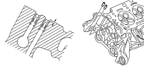
The non return valves are located on the cylinder head in the oil ducts for the phase transformer actuators. The valves should be recessed 2 mm in relation to the plane of the head.
CONSTRUCTION SPECIFICATIONS
The cylinder head is one-piece in aluminium alloy and silicone.
The four valves per cylinder are fitted in guides arranged in a V and driven by two camshafts via tappets.
In addition to the engine oil ducts for lubricating the camshaft supports, a special duct, in the front of the cylinder head, supplies the phase transformer system actuators.
Parts & tools for this job Staging For 2005 Alfa Romeo 159
- PARTEngine gasket setSearch: Alfa Romeo 159 2005 engine gasket set
- TOOLTorque wrenchSearch: 3/8 inch torque wrench
- TOOLFeeler gauge setSearch: feeler gauge set
Links open Amazon search results in a new tab. As an Amazon Associate I earn from qualifying purchases.