
E4023 Auxiliary instrument(dashboard centre) (from 2/99)
- Make
- Alfa Romeo
- Model
- 156 Factory Service Manual
- Year
- 1997–2002
- Section
- Instruments › E4023 Auxiliary instrument(dashboard centre) (from 2/99)
E4023 Auxiliary instrument(dashboard centre) (from 2/99)
Description
The module in the centre of the dashboard includes the:
- fuel gauge, with reserve warning light
- engine coolant temperature gauge, with maximum temperature warning light
- analogue clock.
The fuel level is displayed via electronic circuitry inside the module, which operates the gauge and the reserve warning light (about 7 litres) and "dampens" the signal preventing fluctuations.
During starting, when the ignition is turned on, the warning light comes on for about 4 seconds as a self-test, then goes out. If it flashes and stays on, a fault has been detected in the connection or the level gauge.
The coolant temperature gauge is controlled directly by a sensor on the engine. The maximum temperature warning light is controlled by another signal, independent of the gauge signal, which comes from the engine control unit.
During starting, when the ignition is turned on, the maximum temperature warning light comes on for about 4 seconds as a self-test, then goes out.
The analogue clock consists of a face with hour and minute hands. It is electronic with a quartz oscillator. It is adjusted by means of a button inside the dial.
The centre instrument operates when the ignition is switched ON.
In the "night" position (side lights on), the brightness can be adjusted to three levels by an external button. ( Wiring diagram E2530 INSTRUMENT LIGHTING ).
Description of operation
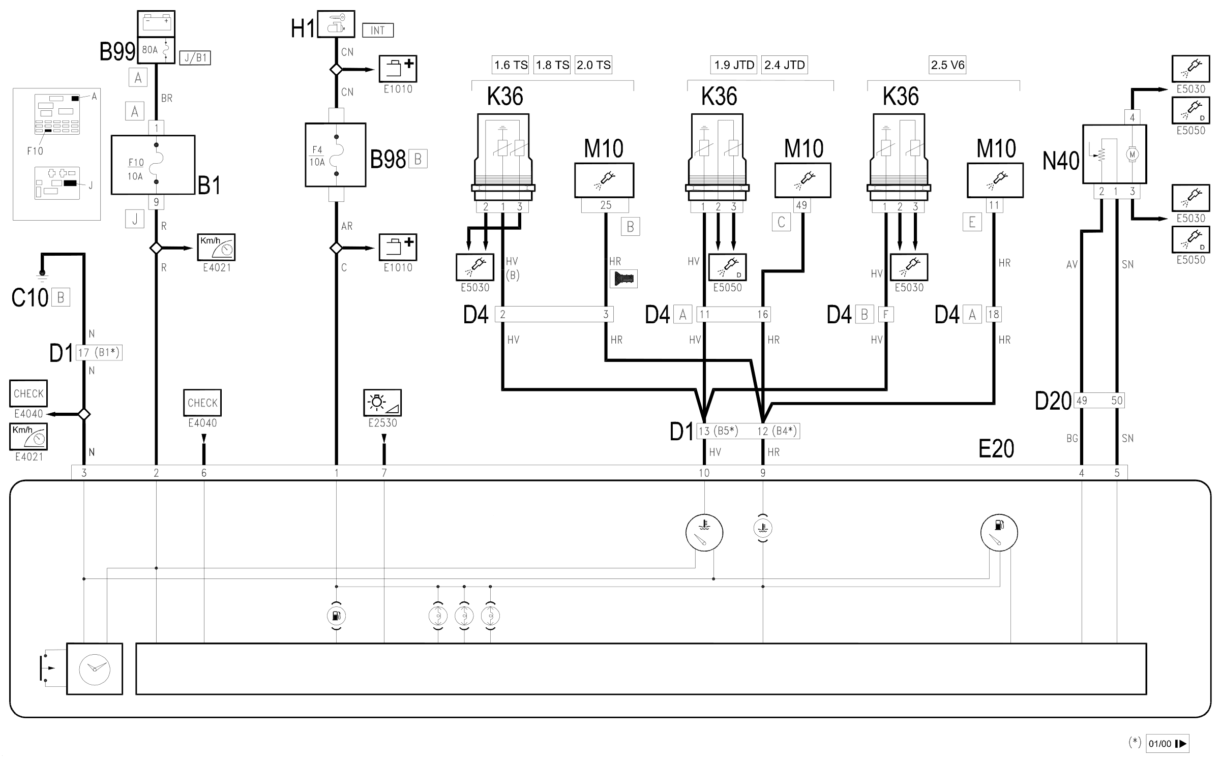
The supply for the centre module E20 arrives directly from the battery. (maxifuse J/B1 of B99) to pin 2 via fuse F10 of junction unit B1; the supply controlled by the ignition (INT) reaches pin 1 of the line protected by fuse F4 of the additional fuse box B98B.
Pin 3 is earthed.
The standard engine temperature sender unit K36 sends a signal proportional to the temperature of the engine coolant (pin 1) to pin 10 of E20. The minimum temperature signal, on the other hand, arrives at pin 9 of E20 from the engine control unit M10.
Pins 4 and 5 of the centre instrument E20 receive signals (positive and negative) coming from the fuel gauge N40 located in the fuel pump unit.
Wiring diagram
Components
| Code | Component | See |
|---|---|---|
| B01 | Junction unit | description 5505A |
| B05 | MAXI FUSE-1 box | |
| B11 | Controls lighting fuse | |
| B98 | Supplementary fuse box | description 5505A |
| B99 | Maxifuse box on battery | |
| C10 | Front left earth | description 5505A |
| D01 | Front / dashboard connection | |
| D04 | Front/engine connection | |
| D20 | Dashboard/rear connection | |
| E20 | Auxiliary instrument | description 5560C |
| H01 | Ignition switch | description 5520A |
| K35 | Coolant temperature sender unit | description 1088E |
| K36 | Engine temperature sender unit | description 1056B |
| K36 | Engine temperature sender unit | description 1060G |
| M10 | Engine management ECU | |
| M10 | Engine management control unit | description 1056B |
| M10 | Engine management control unit | description 1060G |
| N40 | Fuel pump and sender unit | description 1040A |
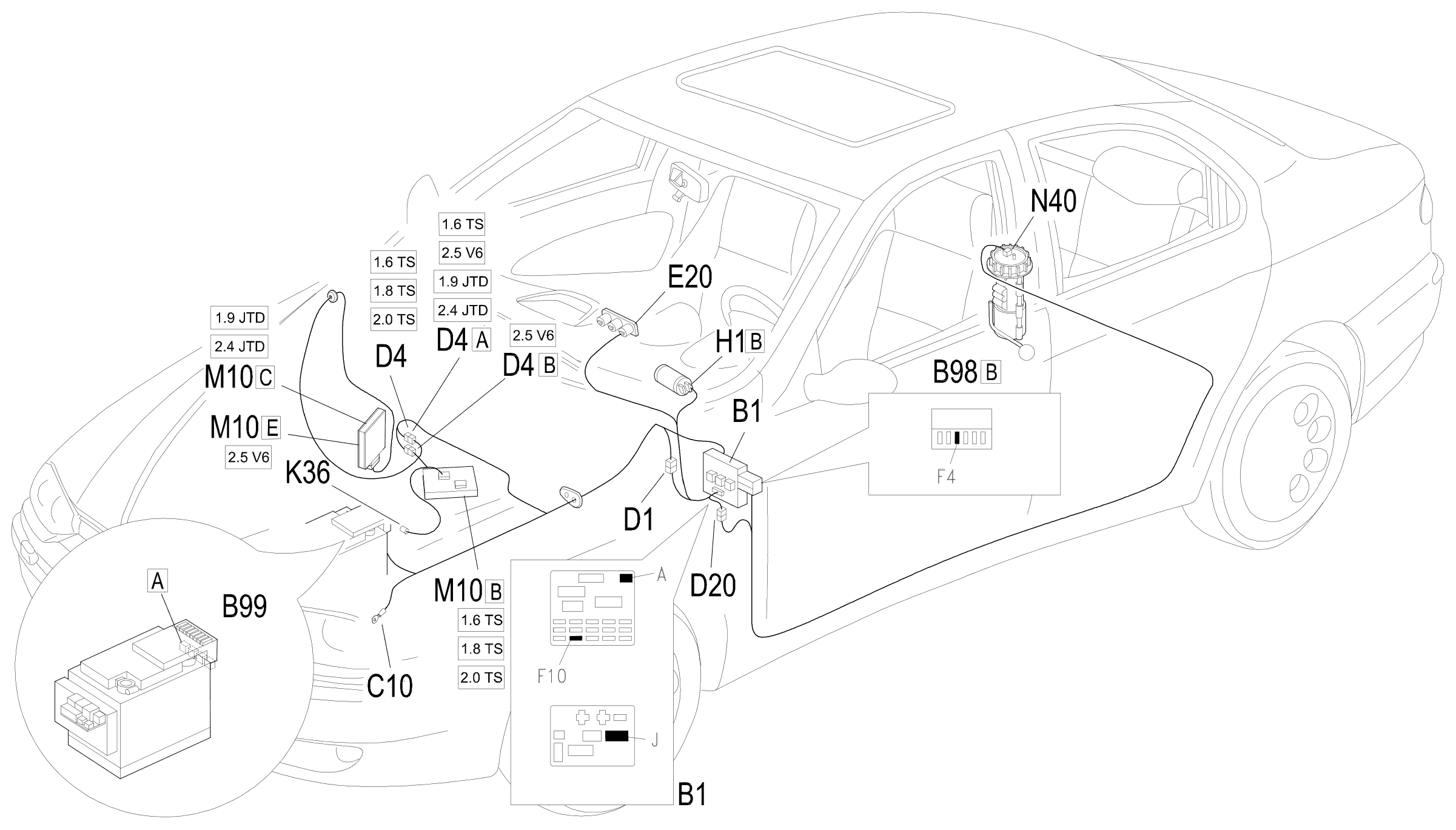
Component location
Parts & tools for this job Staging For 1997 Alfa Romeo 156
- TOOLDigital multimeterSearch: automotive digital multimeter
- PARTAssorted fuse kitSearch: car fuse assortment kit
- TOOLWire crimper and connector kitSearch: wire crimper connector kit
Links open Amazon search results in a new tab. As an Amazon Associate I earn from qualifying purchases.