
E2030 Fog lamp
- Make
- Alfa Romeo
- Model
- 156 Factory Service Manual
- Year
- 1997–2002
- Section
- Exterior lighting › E2030 Fog lamp
E2030 Fog lamp
Description
The vehicle has two additional fog lamps for use in poor visibility conditions.
The rear foglamps are activated by a button on the central console between the seats. A special symbol is lit up when the side lights are on.
The circuit for the fog lights is protected by a special fuse and operated by a special relay, on the right hand side, under the dashboard.
A warning light in the panel (rev counter module) signals that the lamps have been switched on.
The foglamps are enabled under the following conditions:
- the ignition in the ON position
- side lights on.
In addition, if the side lights are switched off, the fog lights are also switched off even if the button is pressed. When the side lights are turned on again, the fog lamps come back on.
If the ignition key is switched OFF and then turned back to the ON position, the operating button must be pressed once again in order to turn the fog lights back on.
This control logic is managed by the integrated services control unit, also on the right hand side, under the dashboard.
Description of operation
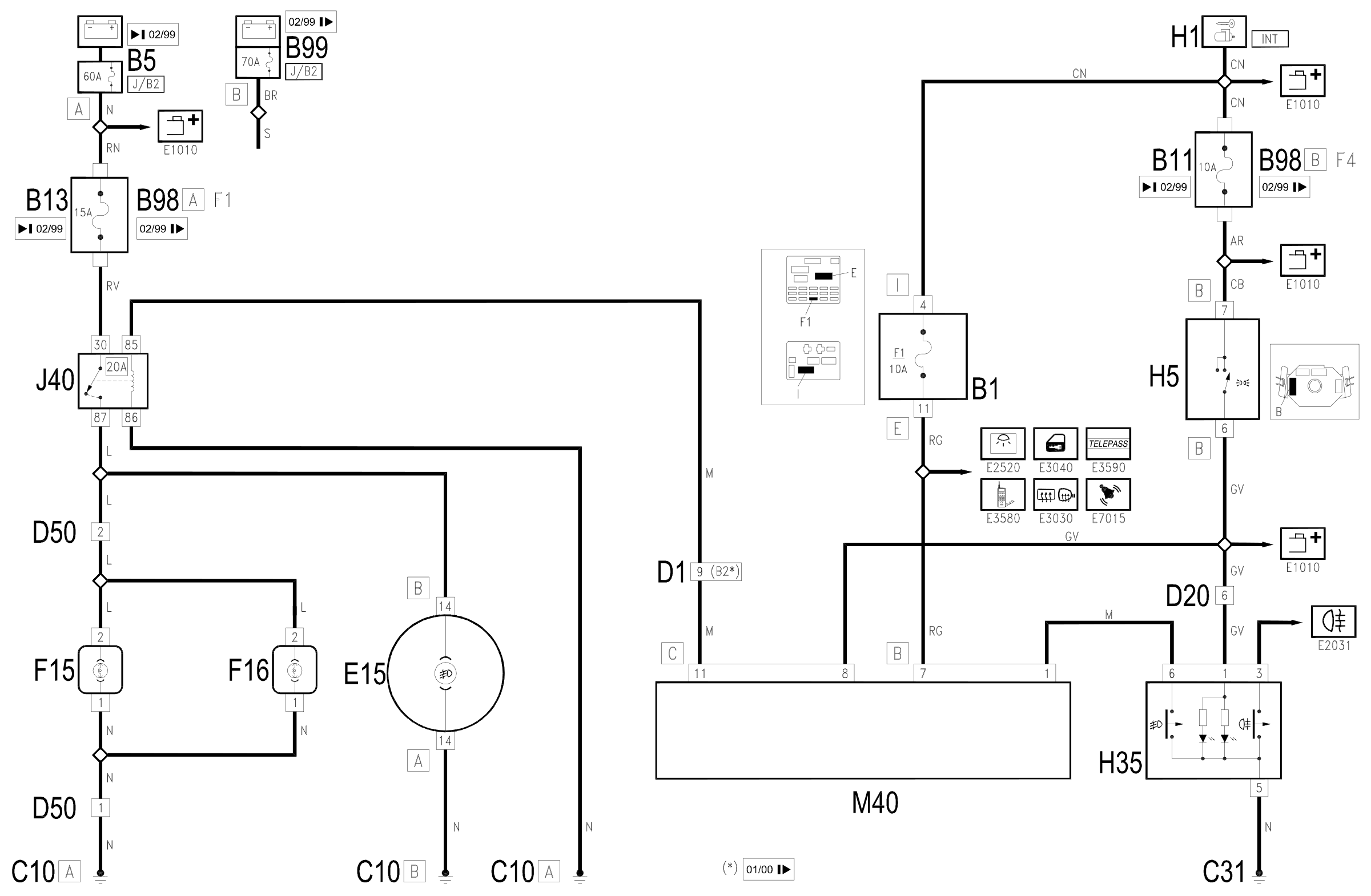
The two front fog lights F15 (left) and F16 (right) are supplied through the fog lights relay J40 by the direct line from the battery - maxifuse J/B2 of B5) up to 2/99 or of B99 from 2/99. - and through the front fog light fuse B13 up to 2/99 or F1 of the additional fuse box B98A from 2/99.
The signal which energizes the coil for the relay J40 arrives from the integrated services control unit M40 (pin 11 of connector C) according to the enablement logic described.
The control unit receives the signal that the side lights are on from the switch for the steering column switch unit H5 (pin 8 of connector C) and the supply is controlled by the ignition (INT) from the line for fuse F1 of the junction unit B1 (pin 7 of connector B).
When the engagement signal also arrives from the button H35 (pin 1 of connector B), the control unit M40 sends the command to the front fog lights relay J40.
The supply line for the two fog lights also sends a signal to the rev counter module E15 (pin 14 of connector B) to light up the "front fog lights on" warning light.
The switch H35 is lit up when the side lights are switched on by means of the line coming from the switch for the steering column switch unit H5.
Wiring diagram
Components
| Code | Component | See |
|---|---|---|
| B01 | Junction unit | description 5505A |
| B05 | MAXI FUSE-1 box | |
| B11 | Controls lighting fuse | |
| B13 | Fog lamp fuse | |
| B98 | Supplementary fuse box | description 5505A |
| B99 | Maxifuse box on battery | |
| C10 | Front left earth | description 5505A |
| C31 | Rear right earth | description 5505A |
| D01 | Front / dashboard connection | |
| D20 | Dashboard/rear connection | |
| D50 | Front fog lamp connection | |
| E15 | Rev counter | description 5560B |
| F15 | Left fog lamp | description 5540D |
| F16 | Right fog lamp | description 5540D |
| H01 | Ignition switch | description 5520A |
| H05 | Steering column switch unit | description 5550A |
| H35 | Switches on central console (front and rear fog lamps) | description 5540D |
| J40 | Foglamp relay | |
| M40 | Integrated services control unit | description 5505A |
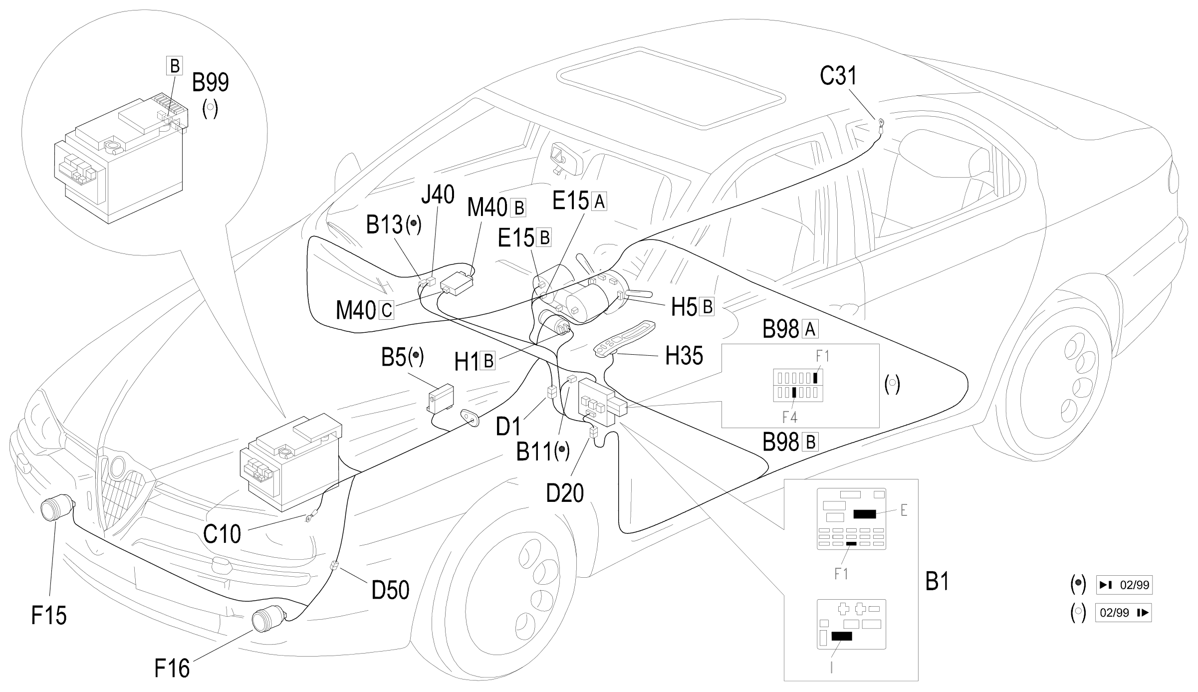
Component location
Parts & tools for this job Staging For 1997 Alfa Romeo 156
- PARTReplacement bulbsSearch: Alfa Romeo 156 1997 bulbs
- TOOLDigital multimeterSearch: automotive digital multimeter
Links open Amazon search results in a new tab. As an Amazon Associate I earn from qualifying purchases.