
E6020 Air conditioner (RH drive adaptation)
- Make
- Alfa Romeo
- Model
- 156 Factory Service Manual
- Year
- 1997–2002
- Section
- Air conditioning › E6020 Air conditioner (RH drive adaptation)
E6020 Air conditioner (RH drive adaptation)
Description
An automatic system manages passenger compartment climate control, i.e. temperature and ventilation with recirculation and air flow orientation.
A dedicated control unit manages system operation by controlling:
- air temperature at outlets;
- fan speed;
- compressor activation (air cooling circuit);
- air recirculation activation;
- "rapid demisting" function;
The control unit sets the above parameters in order to adjust passenger compartment temperature to the required level. The system controls are located outside the control unit housing.
The control unit supplies information on interior and exterior temperature via special sensors.
After processing the information, it adjusts passenger compartment air intake speed by means of the fan motor and air temperature by means of a mixer actuator. It also controls interior air recirculation via a dedicated actuator.
When required, the ECU automatically activates the cooling circuit and dehumidifies the air by operating the air conditioner compressor. ( Wiring diagram E6021 COMPRESSOR ACTIVATION ).
For more details, see DESCRIPTION AND OPERATION: 5040 Air conditioner box and components .
The control unit supply lines are protected by a fuse in the junction unit and by the fuse which protects other supplies controlled by the ignition.
The fan supply lines are protected by a special maxifuse.
The system will only operate when the ignition is turned ON.
Description of operation
The climate control unit M70 receives a supply controlled by the ignition (INT/A) at pin 5 of connector B from the line protected by fuse B10 up to 2/99 or fuse F6 of the additional fuse box B98B from 2/99.; the same line also supplies all the actuators of the system.
The direct supply arrives from the battery (maxifuse J/B1 of B5 up to 2/99 or B99 from 2/99) at pin 10 of connector B through fuse F10 of junction unit B1.
The supply for illuminationg the controls with the side lights on reaches pin 2 of connector B from the line coming from the switch for the steering column switch unit H5 and protected by fuse B11 up to 2/99 or fuse F4 of the additional fuse box B98B from 2/99.
Pin 14 of connector A of M70 is earthed.
Pin 7 of connector B of M70 receives the speedometer signal coming from instrument E10, whilst the outside temperature value is signalled from pin 1 of connector A also at instrument E10.
The sensor which measures the outside temperature is located on the left external rear view mirror P60: the sensor receives a 5 V supply from pin 13 of connector A of M70 and sends the signal to pin 10 of connector A.
Control unit M70 is also connected to sensors K87 (lower treated air), K88 (upper treated air) and K89 (passenger compartment air), which receive a 5 V supply from pin 13 of the connector and send signals to pins 11, 10, 9 respectively of connector A of M70.
Sensor K89 is fitted with a fan motor controlled by the ignition so that the temperature reading is not affected by the motionless and thus warmer air inside the dashboard.
The air conditioning system is equipped with three activators for recirculation (N82), air mixing (N81) and air distribution (N80).
The recirculation actuator N82 is controlled by the control unit M70 from pin 11 of connector B, and there is a current feedback at pin 3 of connector A of M70.
The mixing actuator N81 is controlled by the control unit M70 from pin 6 of connector B, receiving a supply for controlling the potentiometer from pin 2 of connector A and sending a feedback signal to pin 12 of connector B.
The distribution actuator N80 is controlled by the control unit M70 from pin 16 of connector A, receiving a supply for controlling the potentiometer from pin 2 of connector A and sending a feedback signal to pin 9 of connector B.
The electronic governor M72 operates the fan at different speeds: it receives an input signal from the control unit (from pin 3 of connector B) and transforms it into a variable voltage signal that controls the fan. This voltage control is also stabilized, i.e. it is independent of the battery voltage variations. The governor supply is controlled by the ignition (INT/A) from fuse B10 up to 2/99 or fuse F6 of the additional fuse box B98B from 2/99, is connected to earth and also sends the temperature control signal to pin 4 of connector A of M70.
The fan N85 is supplied directly from the battery through the A/C maxifuse line of B6, whilst it is controlled at the different speeds for the voltage signal coming from the electronic governor M72.
The control unit M70 is equipped with a self-test system which can be used by connecting the unit to connector R10: it receives signals from pin 8 of connector B through the diagnostic line.
The commands for switching on the heated rear windscreen, the LED and the "rapid demist" function are transmitted to the integrated services control unit M40 by pin 1 of connector B and pins 6 and 8 of connector A, respectively. It should be remembered that the climate control control unit only "houses" the control button and the LED, but does not in any way affect the heated rear windscreen activation logic. ( Wiring diagram E3030 HEATED REAR WINDOW AND DOOR MIRROR DEFROSTING .)
Pin 7 of connector A controls the activation of the compressor ( Wiring diagram E6021 COMPRESSOR ACTIVATION ).
Wiring diagram
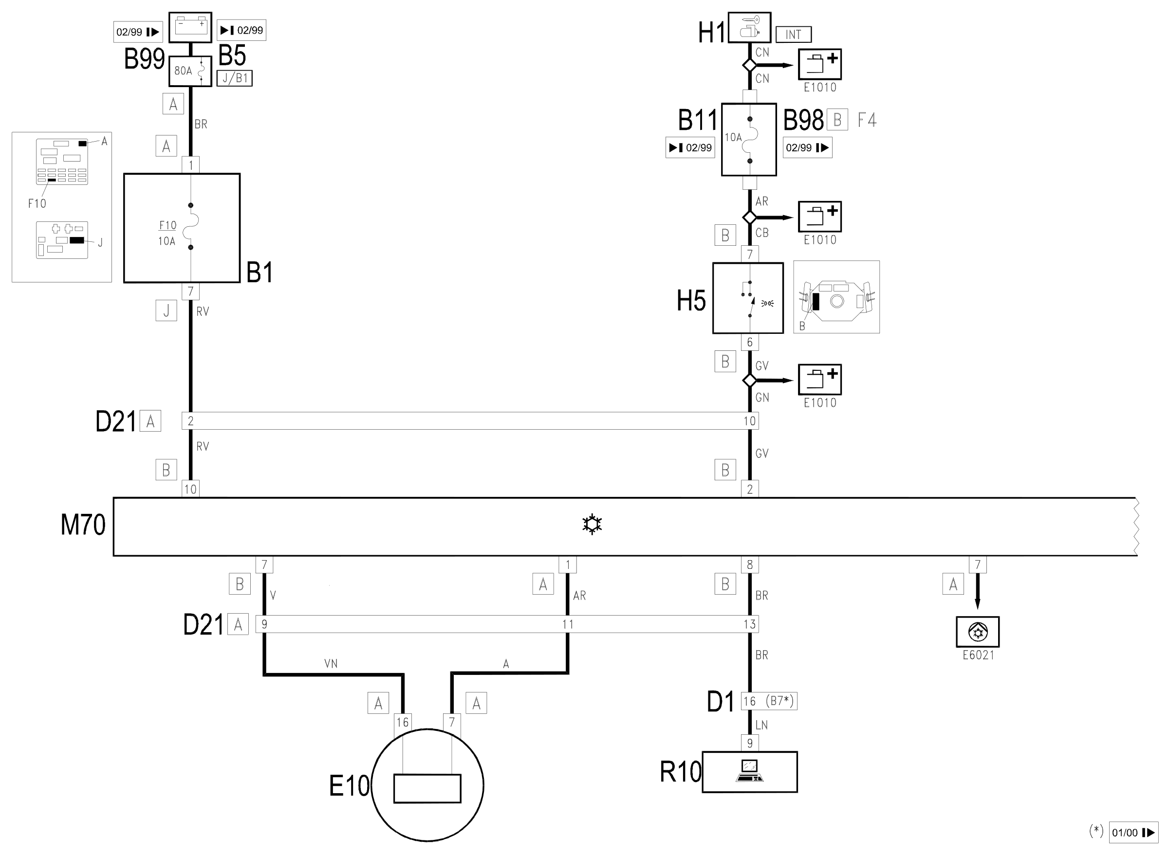
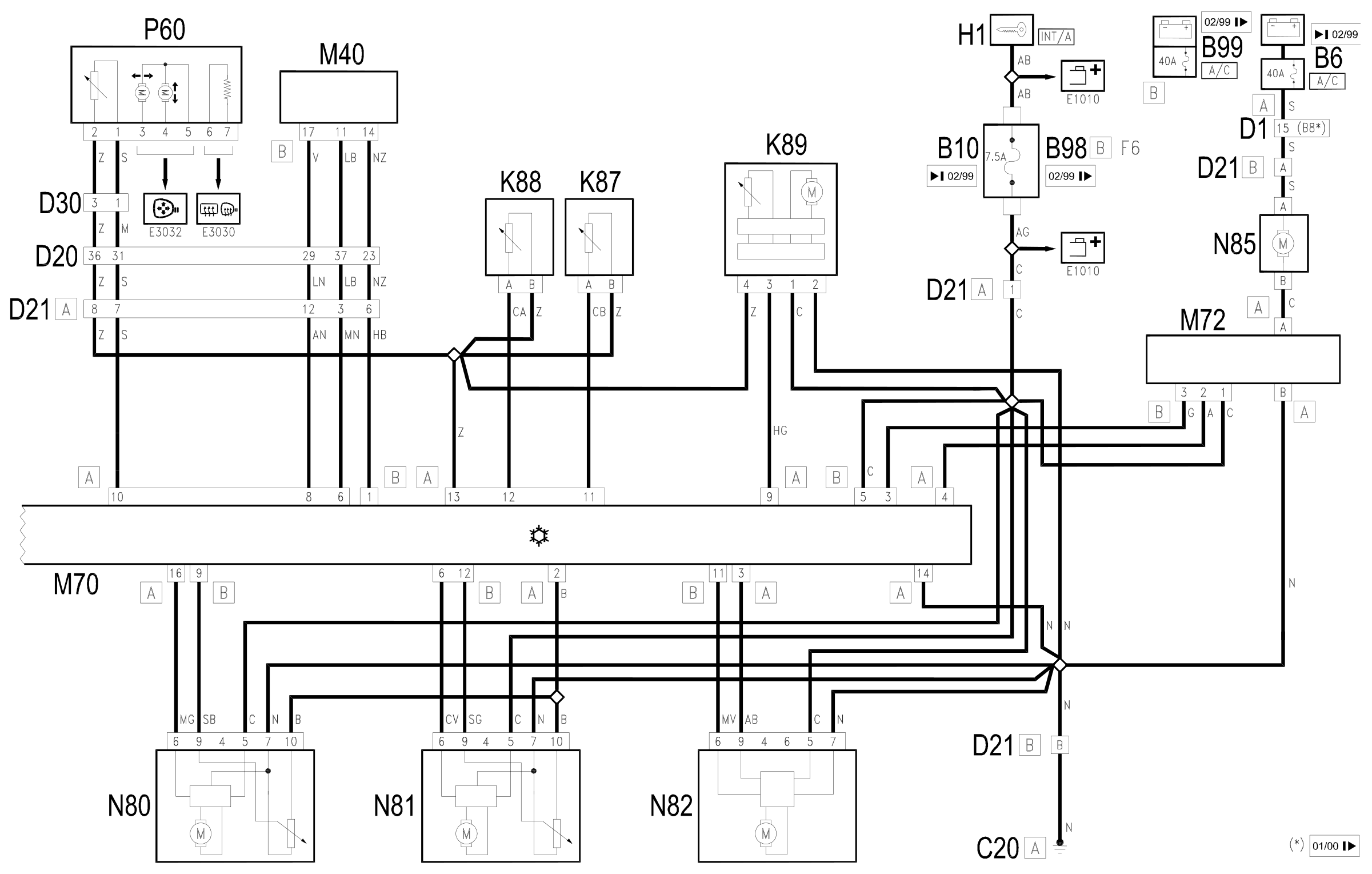
Components
| Code | Component | See |
|---|---|---|
| B01 | Junction unit | description 5505A |
| B05 | MAXI FUSE-1 box | |
| B06 | MAXI FUSE box - 2 | |
| B10 | Key-dependent supply fuse (INT/A) | |
| B11 | Controls lighting fuse | |
| B98 | Supplementary fuse box | description 5505A |
| B99 | Maxifuse box on battery | |
| C20 | Passenger side dashboard earth | description 5505A |
| D01 | Front / dashboard connection | |
| D20 | Dashboard/rear connection | |
| D21 | Dashboard/air conditioning-heater connection | |
| D30 | Rear / front door connection left | |
| D31 | Right front door rear coupling/. | |
| E10 | Speedometer | description 5560B |
| H01 | Ignition switch | description 5520A |
| H05 | Steering column switch unit | description 5550A |
| K86 | Frost sensor | |
| K87 | Lower treated air sensor | description 5010D |
| K88 | Upper treated air sensor | description 5010D |
| K89 | Passenger compartment air sensor | description 5010D |
| M40 | Integrated services control unit | description 5505A |
| M70 | Climate control system control unit | description 5040D |
| M72 | Fan speed' variator | description 5040C |
| N80 | Air distribution actuator | description 5040D |
| N81 | Air mixing actuator | description 5040D |
| N82 | Air intake actuator | description 5020B |
| N85 | Passenger compartment ventilation fan | description 5020A |
| N85 | Passenger compartment ventilation fan | description 5040B |
| P60 | Left door mirror | description 7005R |
| P61 | Right door mirror | description 7005R |
| R10 | Multiple tester connection |
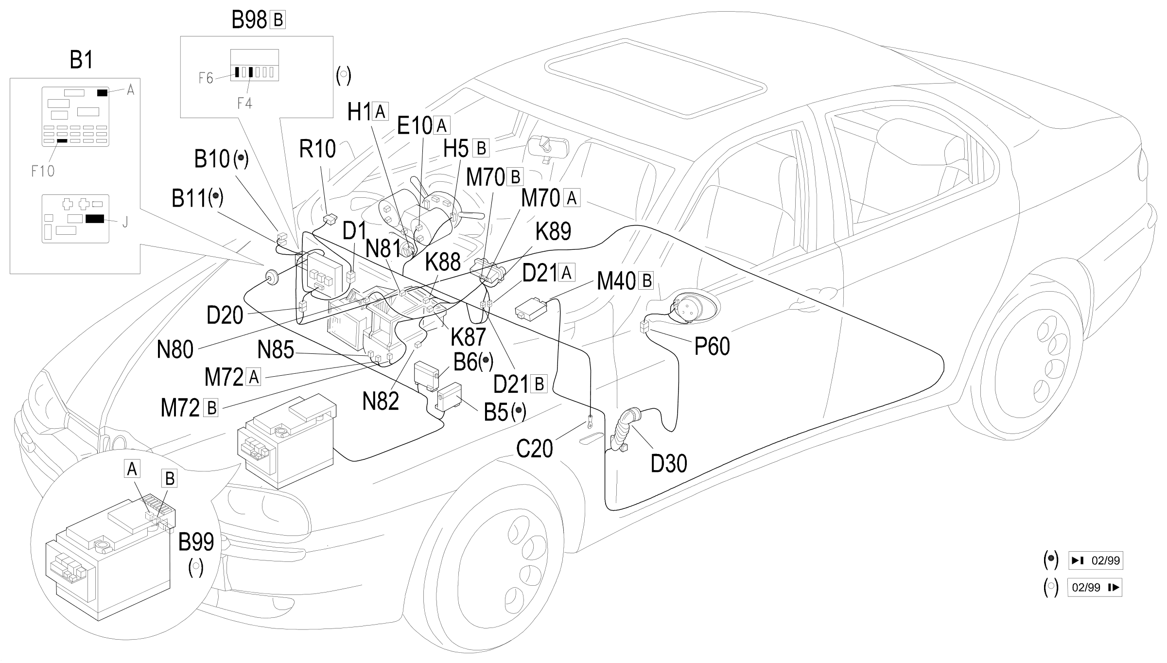
Component location
Parts & tools for this job Staging For 1997 Alfa Romeo 156
- TOOLA/C manifold gauge setSearch: AC manifold gauge set
- TOOLUV leak detection kitSearch: AC UV leak detection kit
- PARTCabin filterSearch: Alfa Romeo 156 1997 cabin filter
Links open Amazon search results in a new tab. As an Amazon Associate I earn from qualifying purchases.