
E6010 Heater
- Make
- Alfa Romeo
- Model
- 156 Factory Service Manual
- Year
- 1997–2002
- Section
- Air conditioning › E6010 Heater
E6010 Heater
Description
The climate control system with heater unit is controlled by means of three knobs in the control panel in the centre of the dashboard:
- the left knob mechanically controls the mixture flap between hot air (red) and cold air (blue);
- the right knob, mechanically operated via a cable, controls the opening of the flaps which regulate the distribution of air flows;
- the centre knob electrically controls the ventilation of the air at four different speeds: 1, 2, 3 and 4. In position 0, the fan is turned off but air still enters due to the dynamic effect of the car's motion.;
- when pressed, the left button activates the air recirculation function by an electrical command; when the button is pressed, the relevant LED comes on. If the button is released, "dynamic" air flows in from the outside
- the right button switches on the heated rear window; when the button is pressed, the relevant LED comes on.
( Wiring diagram E3030 HEATED REAR WINDOW AND DOOR MIRROR DEFROSTING ).
The control switches have ideograms which are lit up when the side lights are on.
For more details, see DESCRIPTION AND OPERATION: 5020 Heater
The system is controlled by means of a special relay located in the distributor duct unit.
The fan supply lines are protected by a special maxifuse and by the fuse which protects other supplies controlled by the ignition. The fan only operates when the ignition is switched ON.
Description of operation
The relay J35 controls the heater fan circuit.
The supply at the relay contact comes from the battery through the line for the A/C maxifuse up to 2/99 or of B99 from 2/99, while the coil energizing is controlled by the ignition (INT/A) from the line protected by fuse B10 up to 2/99 or fuse F6 of the additional fuse box B98B from 2/99.
The relay J35 supplies the control knob H81: this controls the fan at the different speeds through the regulator O30.
The voltage control system varies according to the position of the knob and passes or does not pass through the resistors of the regulator O30 determining the four different voltage signals for the fan N85 which sends outside or recirculation air to the duct/distributor unit at 4 different speeds.
The regulator O30 has a thermal contact which protects against dangerous overvoltages.
The intake of outside air is controlled by the motor N82 which operates the flap between the two extreme positions of "dynamic air" and "recirculation".
The activation of the motor is controlled by the button located in the controls H80: this switch receives a supply controlled by the ignition (INT/A) from the line protected by the fuse B10 up to 2/99 or fuse F6 of the additional fuse box B98B from 2/99.
and is connected to earth: when the supply and earth are reversed, the motor's direction of rotation is reversed. With the recirculation switched on, the LED in the button for H80 also comes on.
The controls unit H80 has ideograms which are lit up when the side lights are on by means of the line coming from the steering column switch unit H5 protected by fuse B11 up to 2/99 or fuse F4 of the additional fuse box B98B from 2/99.
Wiring diagram
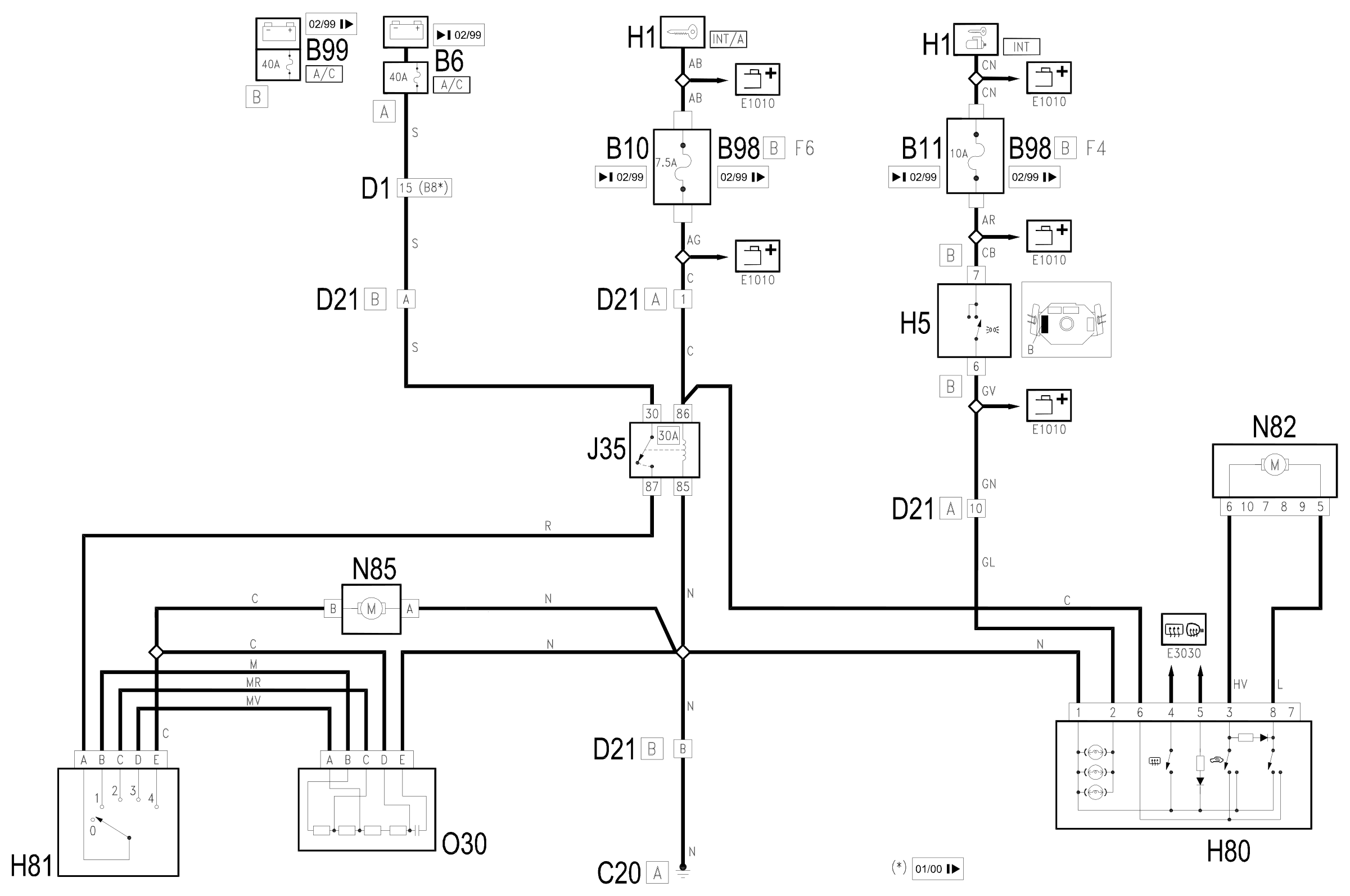
Components
| Code | Component | See |
|---|---|---|
| B06 | MAXI FUSE box - 2 | |
| B10 | Key-dependent supply fuse (INT/A) | |
| B11 | Controls lighting fuse | |
| B98 | Supplementary fuse box | description 5505A |
| B99 | Maxifuse box on battery | |
| C20 | Passenger side dashboard earth | description 5505A |
| C30 | Left rear earth | description 5505A |
| D01 | Front / dashboard connection | |
| D21 | Dashboard/air conditioning-heater connection | |
| H01 | Ignition switch | description 5520A |
| H80 | Climate control controls | description 5020B |
| H81 | Climate control fan control | description 5020B |
| J35 | Interior compartment air electric fan relay | |
| N82 | Air intake actuator | description 5020B |
| N85 | Passenger compartment ventilation fan | description 5020A |
| N85 | Passenger compartment ventilation fan | description 5040B |
| O30 | Passenger compartment air fan adjustment resistor | description 5020A |
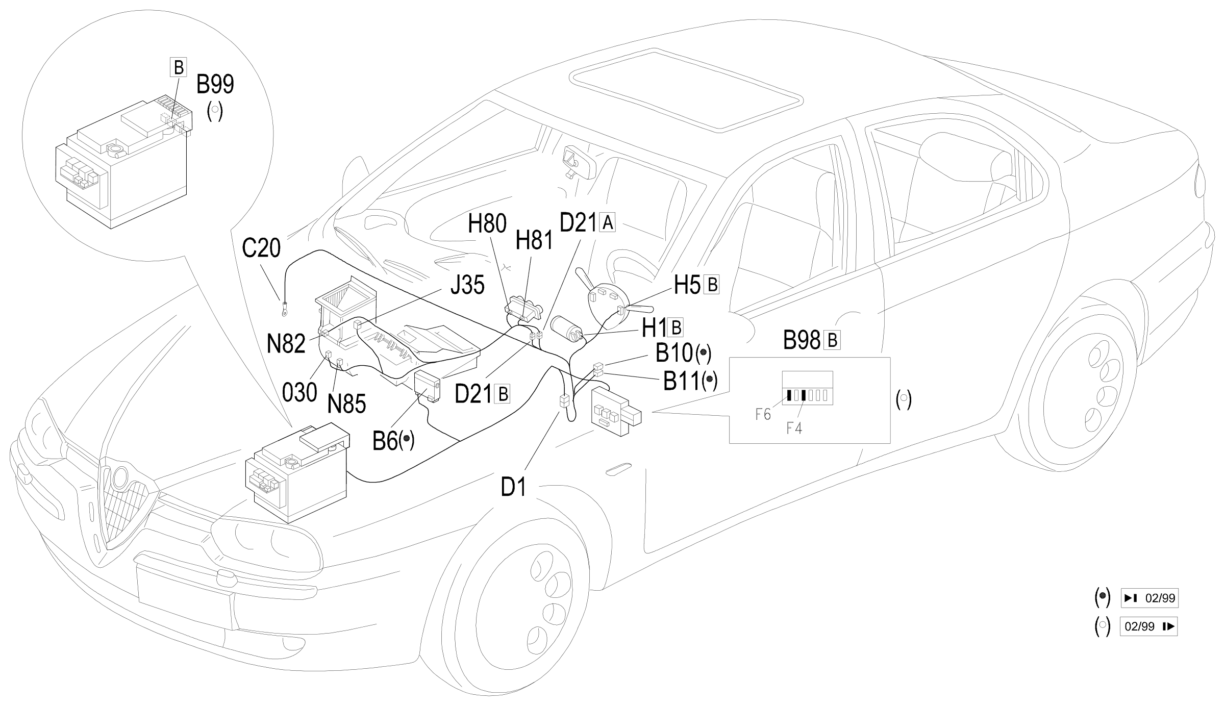
Component location
Parts & tools for this job Staging For 1997 Alfa Romeo 156
- TOOLA/C manifold gauge setSearch: AC manifold gauge set
- TOOLUV leak detection kitSearch: AC UV leak detection kit
- PARTCabin filterSearch: Alfa Romeo 156 1997 cabin filter
Links open Amazon search results in a new tab. As an Amazon Associate I earn from qualifying purchases.