
E6021 Compressor activation
- Make
- Alfa Romeo
- Model
- 147 Factory Service Manual
- Year
- 2000–2002
- Section
- Air conditioning › E6021 Compressor activation
E6021 Compressor activation
Description
When required, the climate control system ECU automatically activates the cooling circuit and dehumidifies the air by operating the air conditioner compressor.
The appropriate button in the climate control control panel enables operation of the air cooling circuit; when the button is pressed the LED comes on.
The above button enables the operation of the air cooling circuit; the actual switching on of the compressor, however, also depends on the climate control system ECU operating strategy: for more details Characteristic of working principle 5040 Air conditioner box and components .
The compressor can also be switched off by the intervention of the four stage pressure switch or by the engine control unit Characteristic of working principle 1056 Fuel injection system .
The compressor is controlled by means of a special relay located in the engine bay control unit. the supply line is protected by a specific fuse, again in the engine bay control unit.
Description of operation
Relay T5 of engine bay control unit B1 controls the compressor activation circuit
The relay supply arrives from the line of maxifuse CVM located on the battery, connector B99, via the line of special fuse F19 of engine bay control unit B1.
The power supply to the coil of relay T5 arrives from main injection relay T9 and ignition-opeated line (15/54) protected by fuse F16, both located in engine bay control unit B1 Wiring diagram E5030 PETROL ENGINES ELECTRONIC CONTROL .
Climate control system ECU M70 sends an enablement signal for compressor activation to 4-stage pressure switch K10: if pressures in the coolant circuit are correct, the signal emerges from the pressure switch and reaches engine control ECU M10, pin 6 of connector A. According to its inner control strategy, control unit M10 send a compressor activation command from pin 31 of connector A which excites relay T5 so that the electromagnet for activation of air conditioner compressor L20 is controlled at 12 V.
Wiring diagram
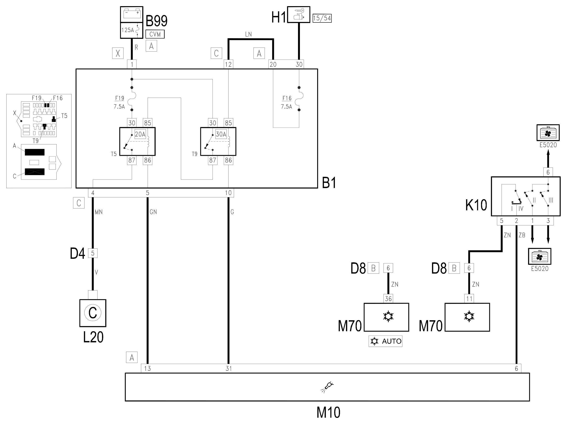
Components
| Code | Component | See |
|---|---|---|
| B01 | Engine compartment junction unit | description 5505A |
| B99 | Maxifuse box on battery | description 5530B |
| D04 | Front / engine coupling | |
| D08 | /Air conditioning -heater front coupling | |
| H01 | Ignition switch | description 5520A |
| K10 | 4 stage pressure switch | description 5540B |
| L20 | Air conditioning compressor "on" electromagnet | description 5040A |
| M01 | Body computer | description 5505A |
| M10 | Engine management ECU | description 1056B |
| M70 | Climate control system control unit | description 5040D |
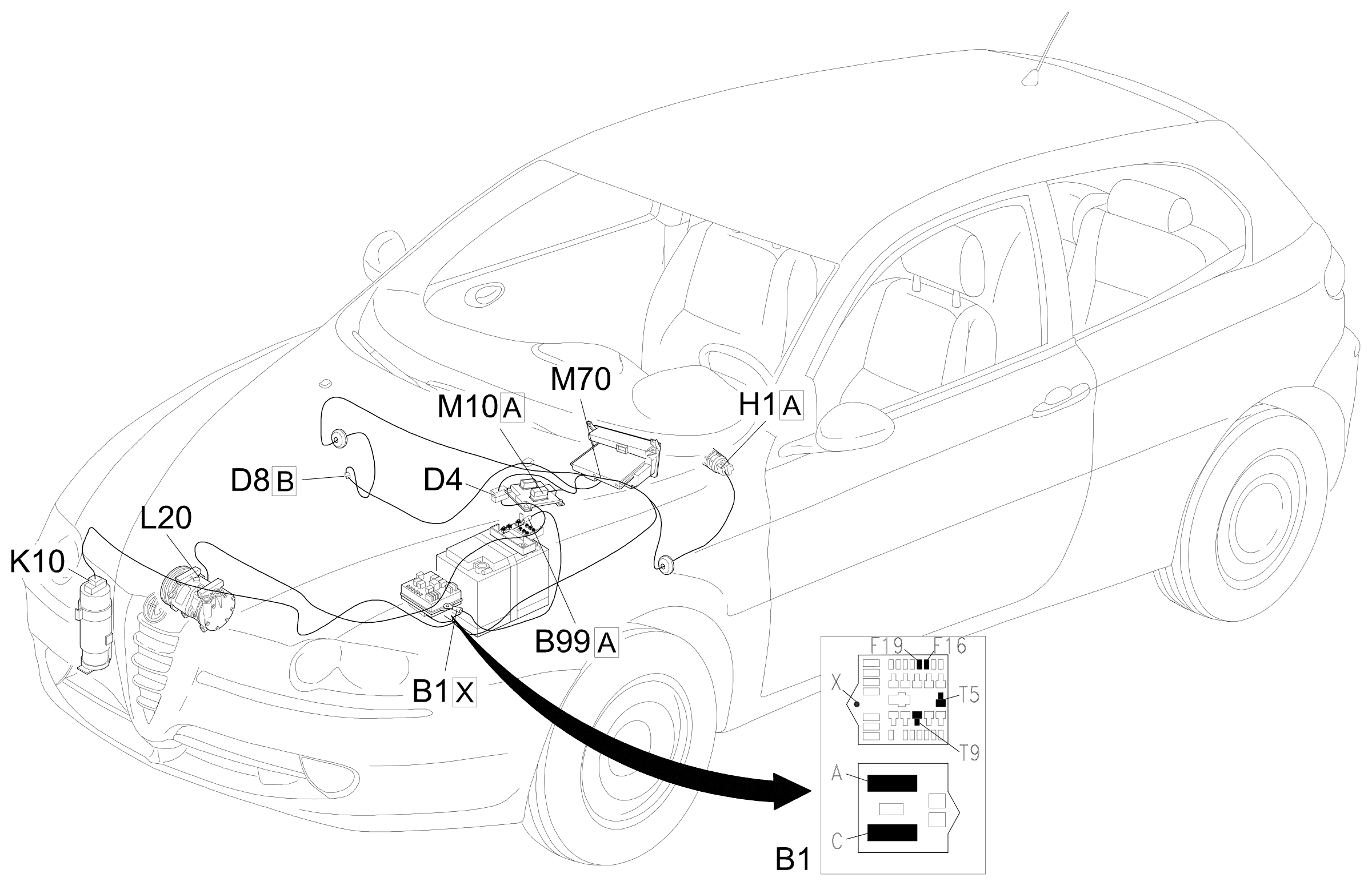
Component location
Parts & tools for this job Staging For 2000 Alfa Romeo 147
- TOOLA/C manifold gauge setSearch: AC manifold gauge set
- TOOLUV leak detection kitSearch: AC UV leak detection kit
- PARTCabin filterSearch: Alfa Romeo 147 2000 cabin filter
Links open Amazon search results in a new tab. As an Amazon Associate I earn from qualifying purchases.