
UNIFIED THREAD IDENTIFICATION
- Make
- Land Rover
- Model
- Defender TD5 Defender
- Section
- UNIFIED THREAD IDENTIFICATION
GENERAL FITTING REMINDERS
7
INFORMATION
COTTER PINS
1. Fit new cotter pins throughout when replacing
any unit.
2. Always fit cotter pins where cotter pins were
originally used. Do not substitute spring
washers: there is always a good reason for the
use of a cotter pin.
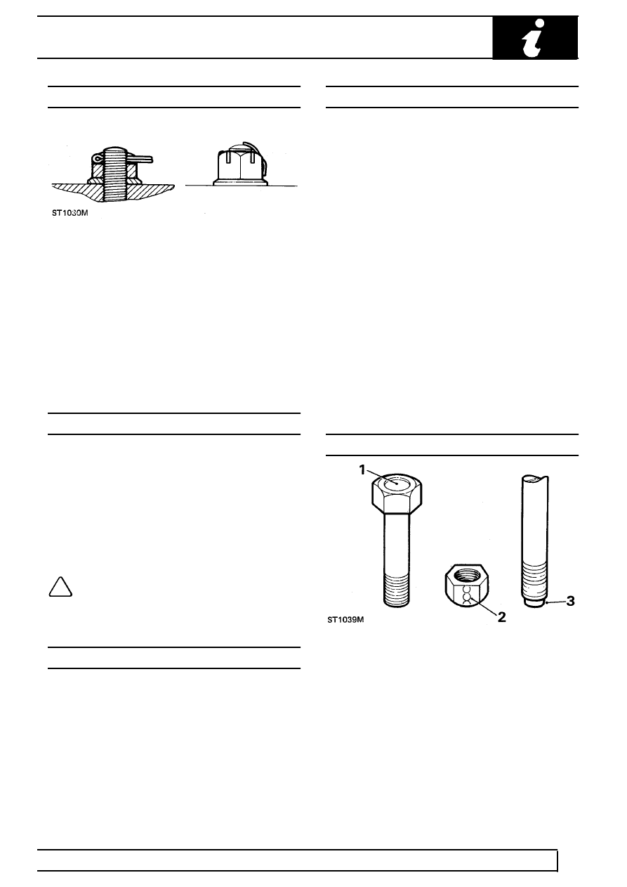
3. All cotter pins should be fitted as shown unless
otherwise stated.
NUTS
1. When tightening a slotted or castellated nut
never loosen it to insert cotter pin or locking wire
except in those recommended cases where this
forms part of an adjustment. If difficulty is
experienced, alternative washers or nuts should
be selected, or washer thickness reduced.
2. Where self-locking nuts have been removed it is
advisable to replace them with new ones of the
same type.
NOTE: Where bearing pre-load is involved
nuts should be tightened in accordance
with special instructions.
LOCKING WIRE
1. Fit new locking wire of the correct type for all
assemblies incorporating it.
2. Arrange wire so that its tension tends to tighten
the bolt heads, or nuts, to which it is fitted.
SCREW THREADS
1. Both UNF and Metric threads to ISO standards
are used. See below for thread identification.
2. Damaged threads must always be discarded.
Cleaning up threads with a die or tap impairs the
strength and closeness of fit of the threads and
is not recommended.
3. Always ensure that replacement bolts are at
least equal in strength to those replaced.
4. Do not allow oil, grease or jointing compound to
enter blind threaded holes. The hydraulic action
on screwing in the bolt or stud could split the
housing.
5. Always tighten a nut or bolt to the recommended
torque value. Damaged or corroded threads can
affect the torque reading.
6. To check or re-tighten a bolt or screw to a
specified torque value first loosen a quarter of a
turn, then re-tighten to the correct value.
7. Oil thread lightly before tightening to ensure a
free running thread, except in the case of
threads treated with sealant/lubricant, and
self-locking nuts.
UNIFIED THREAD IDENTIFICATION
1. Bolts
A circular recess is stamped in the upper surface
of the bolt head.
2. Nuts
A continuous line of circles is indented on one of
the flats of the hexagon, parallel to the axis of
the nut.
3. Studs, Brake Rods, etc.
The component is reduced to the core diameter
for a short length at its extremity.
Parts & tools for this job Staging For Land Rover Defender
- TOOLTorque wrenchSearch: 3/8 inch torque wrench
- TOOLSocket setSearch: socket set metric
- BOOKHaynes manualSearch: Haynes manual Land Rover Defender
Links open Amazon search results in a new tab. As an Amazon Associate I earn from qualifying purchases.