
CYLINDER HEAD FLOW
- Make
- Land Rover
- Model
- Defender TD5 Defender
- Section
- CYLINDER HEAD FLOW
12
ENGINE
36
DESCRIPTION AND OPERATION
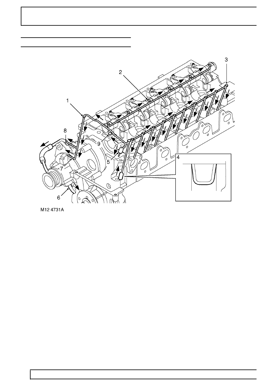
CYLINDER HEAD FLOW
1. Cast-in groove between cylinder head and
camshaft carrier
2. Rocker shaft flow
3. Lash adjuster supply channels (10 off)
4. Non-return valve
5. Chain lubrication jet supply
6. Oil return from vacuum pump
7. Oil supply to timing chain tensioner adjuster
8. Oil supply to vacuum pump
9. Oil supply hole to camshaft sprocket and timing
chain
Oil passes to the cylinder head from the cylinder block via a non-return valve which is included to prevent oil
draining away from the lash adjusters when the engine is switched off.
Oil is passed to a cast-in groove between the top of the cylinder head and the camshaft carrier. The part of the
channel on the top left hand side of the cylinder head has ten cross-drillings which supply oil to the hydraulic lash
adjusters and finger followers. Lubrication oil fed to the lash adjusters passes up through the lash adjuster body
and into the socket of the finger followers. The oil exits the finger followers through a small hole to lubricate the
surfaces between the camshaft lobes and rollers.
Parts & tools for this job Staging For Land Rover Defender
- PARTEngine gasket setSearch: Land Rover Defender engine gasket set
- TOOLTorque wrenchSearch: 3/8 inch torque wrench
- TOOLFeeler gauge setSearch: feeler gauge set
Links open Amazon search results in a new tab. As an Amazon Associate I earn from qualifying purchases.