
CYLINDER BLOCK (page 11 of 12)
- Make
- Land Rover
- Model
- Defender TD5 Defender
ENGINE
23
DESCRIPTION AND OPERATION
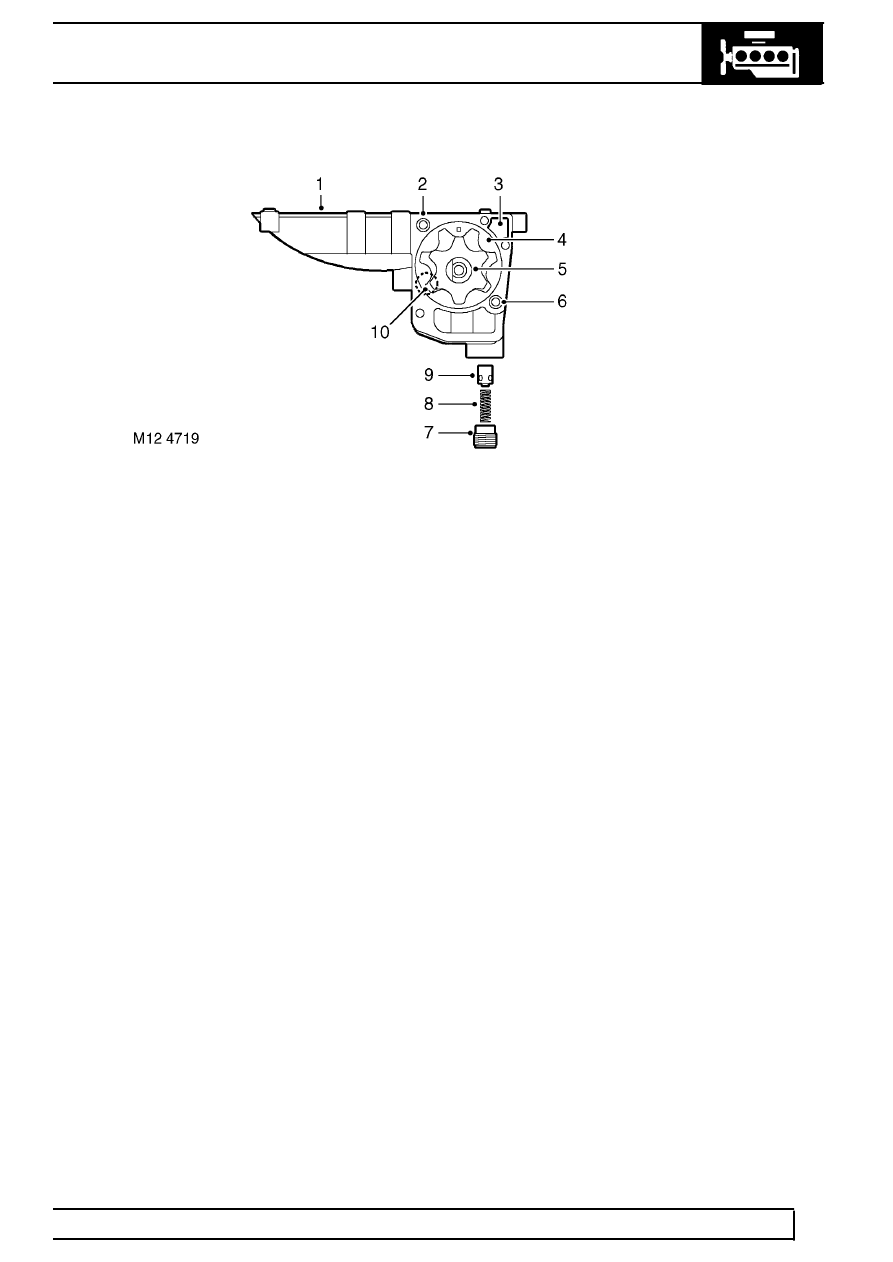
Oil pump
1. Stiffener plate
2. Ring dowel
3. Outlet port
4. Outer rotor
5. Inner rotor
6. Spring dowel
7. Oil pressure relief valve cap
8. Oil pressure relief valve spring
9. Oil pressure relief valve plunger
10. Inlet port
The eccentric rotor oil pump is integrated with the stiffener plate and contains no serviceable parts except for the
pressure relief valve spring. The oil pump drive sprocket is attached to the front of the stiffener plate and is driven
through a chain and sprocket system.
A pressure relief valve is included at the outlet side of the oil pump to restrict oil pressure at high engine speeds by
recirculating oil through the relief valve back around the pump to the inlet. The relief valve and spring is a plunger
type. When oil pressure is great enough to lift the plunger, oil is allowed to escape past the plunger to relieve
pressure and prevent further rise.
Oil is delivered to the pump from the pick-up through a channel in the stiffener plate. The outlet side of the oil
pump delivers pressurised oil flow to the engine block main oil delivery gallery through a port in the stiffener plate.
Piston lubrication jets
Piston lubrication jets are fitted to the cylinder block to provide lubrication to the cylinder walls and to the piston
underskirt for cooling the pistons and lubricating the gudgeon pins. The input port to each lubrication jet mates
with a port provided in each mounting position tapped at the underside of the cylinder block from the main oil
delivery gallery. When oil pressure is sufficient to supply flow through the jets, oil is squirted to the inside of the
cylinder walls to provide piston to wall lubrication and cooling and to the underside of the piston skirt at the bottom
of the piston stroke (gallery cooled piston). The squirt jets also provide splash feed lubrication supply to the small
end bearings of the connecting rods.
Each lubrication jet is fixed to a mounting position on the underside of the engine block by a single Torx screw.
Chain lubrication jet
A chain lubrication jet is located on the front face of the cylinder block, behind the front engine timing chain cover.
The inlet port to the lubrication jet mates with an oil supply port from the cylinder block main oil delivery gallery.
The lubrication jet is fixed to the front of the engine block by a single screw. Additional chain lubrication is provided
by oil supply through a small aperture tapped from the cylinder head oil delivery gallery.
Parts & tools for this job Staging For Land Rover Defender
- PARTEngine gasket setSearch: Land Rover Defender engine gasket set
- TOOLTorque wrenchSearch: 3/8 inch torque wrench
- TOOLFeeler gauge setSearch: feeler gauge set
Links open Amazon search results in a new tab. As an Amazon Associate I earn from qualifying purchases.