
BEARINGS - CONNECTING RODS
- Make
- Land Rover
- Model
- Defender TD5 Defender
- Section
- BEARINGS - CONNECTING RODS
12
ENGINE
30
OVERHAUL
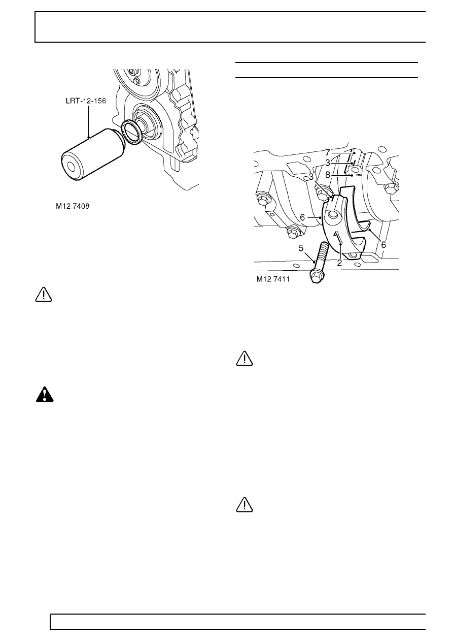
22. Fit oil seal guide, from seal kit, over end of
crankshaft.
23. Fit new oil seal into timing cover using
LRT-12-156.
CAUTION: Oil seal must be fitted dry.
24. Remove LRT-12-156 and oil seal guide.
25. Fit crankshaft pulley, fit crankshaft pulley bolt.
26. Fit LRT-51-003 to crankshaft pulley and secure
with 2 bolts.
27. Using assistance, restrain engine and using a
torque multiplier, tighten crankshaft bolt to 460
Nm (340 lbf.ft) .
WARNING: DUE TO THE HIGH TORQUE
LOADING REQUIRED, IT IS ESSENTIAL
THAT ENGINE IS ADEQUATELY
RESTRAINED.
28. Remove LRT-51-003.
29. Position damper to crankshaft pulley, fit 3 bolts
and tighten to 80 Nm (60 lbf.ft) .
30. Fit sump gasket. See this Section.
31. Fit cylinder head gasket. See this Section.
BEARINGS - CONNECTING RODS
Service repair no - 12.17.16.01
Remove
1. Remove oil pump. See this Section.
2. Mark cylinder reference number on each
connecting rod big-end bearing cap.
3. Make suitable alignment marks between each
big-end bearing cap and connecting rod.
CAUTION: Due to the ’fracture split’
method of manufacturing connecting rods
and bearing caps, incorrect fitting of cap
to connecting rod will damage mating faces and
necessitate replacement of connecting rod
assembly.
4. Rotate crankshaft clockwise until No. 1 big-end
is at BDC.
5. Remove and discard 2 bolts securing No. 1
big-end bearing cap.
6. Remove bearing cap, remove and discard
big-end bearing shell.
7. Push connecting rod up cylinder bore until rod is
clear of crankshaft journal.
CAUTION: Ensure that connecting rod
does not contact cylinder bore or oil squirt
jet and piston does not contact the valves
or EUI’s if the cylinder head is fitted.
Parts & tools for this job Staging For Land Rover Defender
- PARTEngine gasket setSearch: Land Rover Defender engine gasket set
- TOOLTorque wrenchSearch: 3/8 inch torque wrench
- TOOLFeeler gauge setSearch: feeler gauge set
Links open Amazon search results in a new tab. As an Amazon Associate I earn from qualifying purchases.