
ANTI-THEFT ALARM - FROM 02MY (page 2 of 9)
- Make
- Land Rover
- Model
- Defender TD5 Defender
86
ELECTRICAL
4
DESCRIPTION AND OPERATION
Door and Bonnet Switches
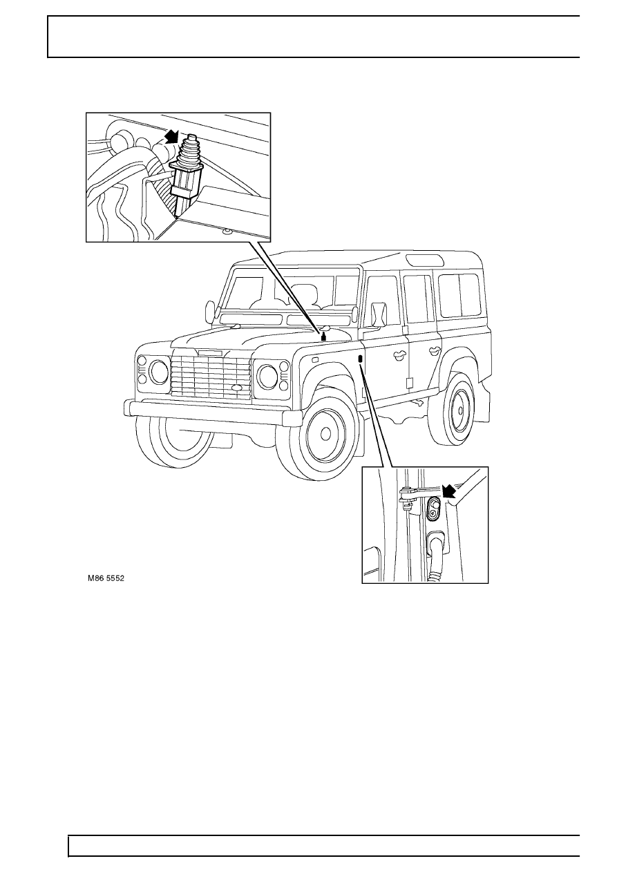
The bonnet switch is located at the rear of the bonnet aperture on the bulkhead. The door switches are located on
the ’A’ posts for the front doors, the ’B’ posts for the rear doors and on the inside face of the tail door aperture.
The drivers door switch and the bonnet switch are connected to the anti-theft alarm ECU on individual single
wires. The remaining passenger doors and, if applicable, the tail door are jointly connected on a single wire to the
ECU. If a fault occurs which involves incorrect mislock signals, alarm triggers and interior lamp operation, the door
switch earth may be the cause of incorrect operation.
If any door or the bonnet is opened, the switch closes and completes an earth path to the anti-theft alarm ECU.
This completed earth path input is sensed by the ECU, which, if armed, will sound the BBUS or alarm sounder.
The ECU also controls, via the door switches and ignition on/off signals, the operation of the interior lamps.
Parts & tools for this job Staging For Land Rover Defender
- TOOLDigital multimeterSearch: automotive digital multimeter
- PARTAssorted fuse kitSearch: car fuse assortment kit
- TOOLWire crimper and connector kitSearch: wire crimper connector kit
Links open Amazon search results in a new tab. As an Amazon Associate I earn from qualifying purchases.