
DESCRIPTION (page 6 of 6)
- Make
- Land Rover
- Model
- Defender TD5 Defender
CLUTCH
11
DESCRIPTION AND OPERATION
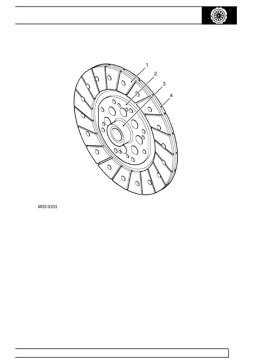
Drive plate
1. Friction material
2. Inner plate
3. Hub
4. Spring steel plate
The drive plate is of the rigid centre type and is sandwiched between the flywheel and the pressure plate. The
drive plate has a splined hub which engages with the splines on the primary drive shaft from the gearbox. The hub
is attached to an inner plate which is pressed onto the hub. A spring steel plate is riveted to the inner plate with
eight rivets and provides the attachment surface for the drive plate friction material. The spring steel plate allows
some axial compliance and contributes to smooth clutch operation. The friction material comprises two 267 mm
(10.5 in.) discs which are secured with rivets to each side of the spring steel plate. The rivets are installed through
recessed holes in the disc and emerge in recessed holes in the opposite disc.
Parts & tools for this job Staging For Land Rover Defender
- PARTClutch kitSearch: Land Rover Defender clutch kit
- TOOLClutch alignment toolSearch: clutch alignment tool
- FLUIDGear oilSearch: Land Rover Defender manual gearbox oil
Links open Amazon search results in a new tab. As an Amazon Associate I earn from qualifying purchases.