
Engine - position on stand and remove
- Make
- Lancia
- Model
- Ypsilon Factory Service Manual
- Year
- 2003–2011
- Section
- Engine and power unit › Engine - position on stand and remove
Engine - position on stand and remove
Dismantling
Support the engine in order to work on it in safety.
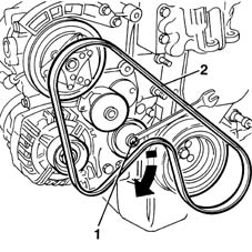
1. Use the automatic belt tensioner to slacken auxiliary drivebelt tension.
2. Remove the auxiliary drivebelt by prising off its drive pulleys.
Dismantling
Support the engine in order to work on it in safety.
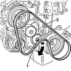
1. Use the automatic belt tensioner to slacken auxiliary drivebelt tension.
2. Remove the auxiliary drivebelt by prising off its drive pulleys.
Dismantling
Support the engine in order to work on it in safety.
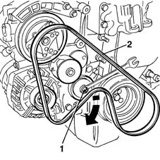
1. Use the automatic belt tensioner to slacken auxiliary drivebelt tension.
2. Remove the auxiliary drivebelt by prising off its drive pulleys.
SOLUTION A
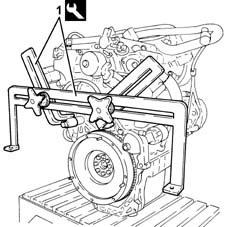
1. Fit the two universal tool brackets.
| Name | Country | |
|---|---|---|
| 1 | Bracket | 1.861.001.034 |
1. Disconnect the electrical connections (1a) from the air conditioner compressor and (1b) from the alternator.
| Name | Connector | |
|---|---|---|
| 1a | Air conditioning compressor electro-magnet | L20 |
| Name | Connector | |
|---|---|---|
| 1b | Alternator | A10 |
2. Remove mount (2a) with alternator and air conditioner compressor by undoing nuts (2b) and bolts (2c).
3. Remove the engine mount, timing side.
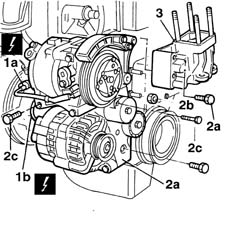
1. Disconnect the electrical connections (1a) from the air conditioner compressor and leads (1b) from the alternator.
| Name | Connector | |
|---|---|---|
| 1a | Air conditioning compressor electro-magnet | L20 |
| Name | Connector | |
|---|---|---|
| 1b | Alternator | A10 |
2. Remove mount (2a) with alternator and air conditioner compressor by undoing nuts (2b) and bolts (2c).
3. Remove the engine mount, timing side.
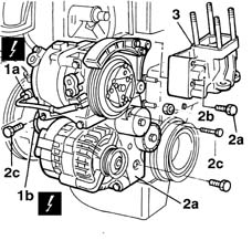
1. Disconnect the electrical connections (1a) from the air conditioner compressor and leads (1b) from the alternator.
| Name | Connector | |
|---|---|---|
| 1a | Air conditioning compressor electro-magnet | L20 |
| Name | Connector | |
|---|---|---|
| 1b | Alternator | A10 |
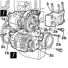
2. Undo the nuts (2a) and the bolts (2b), then remove the mounting complete with air conditioning compressor (2c).
3. Remove the engine mount, timing side.
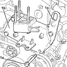
1. Undo the bolts (1a) and remove the timing side rigid engine support (1b) complete with engine lifting bracket (1c).
1. Disconnect the electrical connections from the ignition coils.
| Name | Connector | |
|---|---|---|
| 1 | Ignition 'coil | A30 |
2. Disconnect the HT leads from the spark plug sockets.
3. Remove the ignition coil.
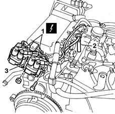
1. Disconnect the electrical connections for the ignition coil.
| Name | Connector | |
|---|---|---|
| 1 | Ignition 'coil | A30 |
2. Disconnect the HT leads from the spark plug sockets.
3. Remove the ignition coil.
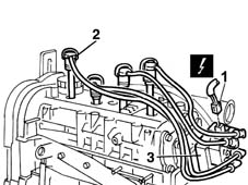
1. Undo the fixing bolt (1a) and extract the timing sensor (1b).
2. Disconnect the electrical connections (2a) for the ignition coils, then undo the bolt (2b) fixing the coils to the cylinder head.
| Name | Connector | |
|---|---|---|
| 2a | Ignition 'coil | A30 |
3. Remove the ignition coils.
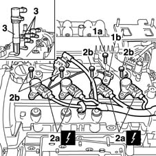
1. Fit the two universal tool brackets.
| Name | Country | |
|---|---|---|
| 1 | Bracket | 1.861.001.032 |
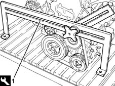
Secure and support the engine for hoisting using a hydraulic hoist fitted with suitable chains.
1. Position the engine bracket on the timing side.
| Name | Country | |
|---|---|---|
| 1 | Bracket | 1.861.001.032 |
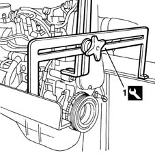
Secure and support the engine for hoisting using a hydraulic hoist fitted with suitable chains.
1. Position the engine bracket on the timing side.
| Name | Country | |
|---|---|---|
| 1 | Bracket | 1.861.001.032 |
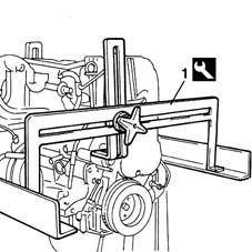
Secure and support the engine for hoisting using a hydraulic hoist fitted with suitable chains.
1. Position the engine bracket on the timing side.
| Name | Country | |
|---|---|---|
| 1 | Bracket | 1.861.001.032 |
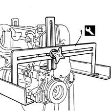
Secure and support the engine using a hydraulic hoist fitted with suitable chains.
Position the engine on the overhaul stand using the universal tool fitted previously.
| Name | Country | |
|---|---|---|
| Rotating stand | 1.861.000.000 |
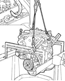
1. Position the engine bracket on the flywheel side.
| Name | Country | |
|---|---|---|
| 1 | Bracket | 1.861.001.034 |
Secure the engine to the overhaul stand using service bolts.
Release the engine from the hoist.
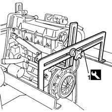
1. Position the engine bracket on the flywheel side.
| Name | Country | |
|---|---|---|
| 1 | Bracket | 1.861.001.034 |
Secure the engine to the overhaul stand using service bolts.
Release the engine from the hoist.
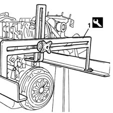
1. Position the engine bracket on the flywheel side.
| Name | Country | |
|---|---|---|
| 1 | Bracket | 1.861.001.034 |
Secure the engine to the overhaul stand using service bolts.
Release the engine from the hoist.
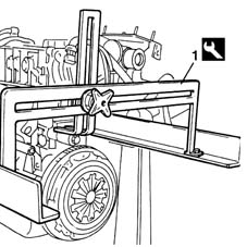
Release the engine from the hydraulic lift fastenings.
Secure and support the engine using a hydraulic hoist fitted with suitable chains.
Undo the fastenings securing the universal tool to the overhaul stand, then position the engine on a suitable workbench using the hydraulic lift.
Undo the fastenings and remove the universal tool from the engine.
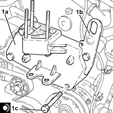
1. Place the timing side rigid engine support (1a), complete with engine lifting bracket (1b), in position and secure it tightening the bolts (1c) to the recommended torque.
| Fastening | Component | Ø | Value (daNm) | |
|---|---|---|---|---|
| 1c | Bolt | ENGINE MOUNT TIMING SIDE | M10 | (Upper engine crankcase side) 5.7 ÷ 6.3 |
Reassembling
Secure and support the engine for hoisting using a hydraulic hoist fitted with suitable chains.
Undo the fixing bolts and remove the engine mounting brackets on the rotating stand.
| Name | Country | |
|---|---|---|
| Bracket | 1.861.001.032 |
| Name | Country | |
|---|---|---|
| Bracket | 1.861.001.034 |
Undo the fixings and remove the supporting tools from the engine, then place them down.
Fit the ignition coil
Fit the spark plug HT leads into their seats.
Connect the electrical connection to the ignition coil.
| Name | Connector | |
|---|---|---|
| Ignition 'coil | A30 |
Fit the timing side engine mount
| Fastening | Component | Ø | Value (daNm) | |
|---|---|---|---|---|
| Bolt | ENGINE MOUNT TIMING SIDE | M10 x 1.25 | 6 |
Fit the mount with alternator and air conditioner compressor.
| Fastening | Component | Ø | Value (daNm) | |
|---|---|---|---|---|
| Bolt | ALTERNATOR SUPPORT | M10 x 1.25 | 5 |
| Fastening | Component | Ø | Value (daNm) | |
|---|---|---|---|---|
| Nut | ALTERNATOR SUPPORT | M10 x 1.25 | 5 |
Connect the alternator leads.
| Name | Connector | |
|---|---|---|
| Alternator | A10 |
Connect the electrical connection to the air conditioner compressor
| Name | Connector | |
|---|---|---|
| Air conditioning compressor electro-magnet | L20 |
Fit the auxiliary drivebelt to the drive pulleys, then turn the automatic tensioner and fit the belt.
Remove the hooks and support devices positioned previously.
Reassembling
Secure and support the engine for hoisting using a hydraulic hoist fitted with suitable chains.
Undo the fixing bolts and remove the engine mounting brackets on the rotating stand.
| Name | Country | |
|---|---|---|
| Bracket | 1.861.001.032 |
| Name | Country | |
|---|---|---|
| Bracket | 1.861.001.034 |
Undo the fixings and remove the supporting tools from the engine, then place them down.
Fit the ignition coils in the seats in the cylinder head, then tighten the fixing bolts.
Fit the timing sensor on the cylinder head and tighten the fixing bolt.
Connect the electrical connections to the ignition coils.
| Name | Connector | |
|---|---|---|
| Ignition 'coil | A30 |
Fit the timing side engine mount
| Fastening | Component | Ø | Value (daNm) | |
|---|---|---|---|---|
| Bolt | ENGINE MOUNT TIMING SIDE | M10 x 1.25 | 6 |
Fit the mount with alternator and air conditioner compressor.
| Fastening | Component | Ø | Value (daNm) | |
|---|---|---|---|---|
| Bolt | ALTERNATOR SUPPORT | M10 x 1.25 | 5 |
| Fastening | Component | Ø | Value (daNm) | |
|---|---|---|---|---|
| Nut | ALTERNATOR SUPPORT | M10 x 1.25 | 5 |
Connect the alternator leads.
| Name | Connector | |
|---|---|---|
| Alternator | A10 |
Connect the electrical connection to the air conditioner compressor
| Name | Connector | |
|---|---|---|
| Air conditioning compressor electro-magnet | L20 |
Fit the auxiliary drivebelt to the drive pulleys, then turn the automatic tensioner and fit the belt.
Remove the hooks and support devices positioned previously.
SOLUTION B
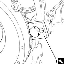
1. Keep the flywheel lock in position. Refer to op. 1004D10 power unit (manual gearbox), removed, remove and re-build
| Name | Country | |
|---|---|---|
| 1 | Counter-torque | 1.860.846.000 |
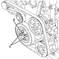
1. Loosen the crankshaft pulley fixing bolts.
2. With the engine timed Refer to op. 1004D10 power unit (manual gearbox), removed, remove and re-build loosen the left hand bolt fixing the pulley mounting flange on the crankshaft.
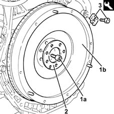
1. Undo the bolts (1a) and remove the engine flywheel (1b).
2. Remove the flange.
The engine flywheel bolts are pretreated with sealant and must therefore be replaced whenever they are removed.
3. Remove the flywheel lock.
| Name | Country | |
|---|---|---|
| 3 | Counter-torque | 1.860.846.000 |
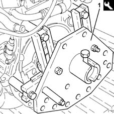
1. Fit the universal tool on the cylinder block/crankcase.
| Name | Country | |
|---|---|---|
| 1 | Rotating overhaul stand | 1.871.001.000 |
Secure and support the engine using a hydraulic hoist fitted with suitable chains.
Position the engine on the overhaul stand using the universal tool fitted previously.
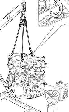
Release the engine from the hydraulic lift fastenings.
Secure and support the engine using a hydraulic hoist fitted with suitable chains.
Undo the fastenings securing the universal tool to the overhaul stand, then position the engine on a suitable workbench using the hydraulic lift.
Undo the fastenings and remove the universal tool from the engine.
1. Fit the flywheel lock.
| Name | Country | |
|---|---|---|
| 1 | Counter-torque | 1.860.846.000 |
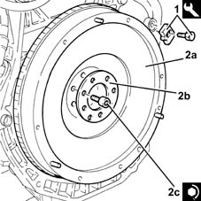
2. Place the engine flywheel (2a) complete with flange (2b) in position and secure it tightening the new bolts (2c) to the recommended torque.
| Fastening | Component | Ø | Value (daNm) | |
|---|---|---|---|---|
| 2c | Bolt | FLYWHEEL | M8 | (Crankshaft side) 4.0 ÷ 4.8 |
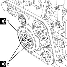
1. With the timing template fitted on the exhaust side camshaft Refer to op. 1004D10 power unit (manual gearbox), removed, remove and re-build, tighten the left hand bolt fixing the pulley mounting flange to the crankshaft.
| Fastening | Component | Ø | Value (daNm) | |
|---|---|---|---|---|
| 1 | Left hand thread bolt | PULLEY SUPPORT FLANGE ON CRANKSHAFT | M14 | (Crankshaft side) 21.9 ÷ 24.2 |
2. Tighten the bolts fixing the crankshaft pulley to the recommended torque.
| Fastening | Component | Ø | Value (daNm) | |
|---|---|---|---|---|
| 2 | Bolt | CRANKSHAFT PULLEY | M8 | (Crankshaft flange side) 2.3 ÷ 2.8 |
Parts & tools for this job Staging For 2003 Lancia Ypsilon
- PARTEngine gasket setSearch: Lancia Ypsilon 2003 engine gasket set
- TOOLTorque wrenchSearch: 3/8 inch torque wrench
- TOOLFeeler gauge setSearch: feeler gauge set
Links open Amazon search results in a new tab. As an Amazon Associate I earn from qualifying purchases.