
Turbocharger - exhaust manifold - hose connected to exhaust pipe - r.r.
- Make
- Lancia
- Model
- Thesis Factory Service Manual
- Year
- 2002–2009
- Section
- Engine supercharging system › Turbocharger - exhaust manifold - hose connected to exhaust pipe - r.r.
TURBOCHARGER - EXHAUST MANIFOLD - HOSE CONNECTED TO EXHAUST PIPE - R.R.
Removing
See in Op. 7055B54 PROTECTION/GUARD under engine - R.R.
1. Disconnect the air inlet house between the turbocharger and the heat exchanger, turbocharger side.
2. Disconnect the turbochrger air inlet hose.
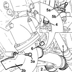
3. Undo the fixing bolts (3a) and remove the protection (3b) for the sump oil return pipe from the turbocharger.
4. Disconnect the sump oil return pipe from the turbochager on the crankcase side.
5. Undo the connector (5a) and disconnect the turbocharger oil supply pipe (5b), crankcase side.
6. Undo the nuts fixing the hose connecting the turbocharger and the exhaust pipe.
See in Op. 1016A10
See in Op. 1048A10
See in Op. 1088E10
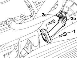
1. Undo the bolts fixing the rigid exhaust gas supply pipe to the exhaust manifold.
2. Loosen the retaining band (2a) and remove the front section (2b) of the rigid exhaust gas supply pipe.
- Disconnect the vacuum pipe from the turbocharger variable geometry management solenoid valve located on the lower crossmember.
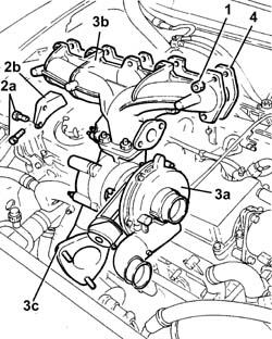
1. Undo the nuts fixing the exhaust manifold to the cylinder head.
2. Undo the bolts (2a) fixing the turbocharger mounting bracket (2b) to the crankcase, then remove it.
3. Remove the turbocharger (3a) complete with exhaust manifold (3b) and hose connected to the exhaust pipe (3c).
4. Remove the exhaust manifold gasket from the studs on the cylinder head.
Refitting
- Fit the new exhaust manifold gasket in the special housing on the cylinder head.
- Fit the turbocharger-exhaust manifold assembly.
- Tighten the self-locking nuts fixing the exhaust manifold to the cylinder head.
| Value - daNm | Fastening | Component | Ø | |
|---|---|---|---|---|
| 2.5 | Nuts | EXHAUST MANIFOLD/S | M8 |
- Fit the bracket for the turbocharger and fasten it to the crankcase and to the turbocharger.
- Fit the bracket for the turbocharger and fasten it to the crankcase and to the turbocharger tightening the fastenings to torque.
| Value - daNm | Fastening | Component | Ø | |
|---|---|---|---|---|
| 2.5 | Nut | EXHAUST MANIFOLD RETAINING BRACKET | M8 |
| Value - daNm | Fastening | Component | Ø | |
|---|---|---|---|---|
| 2.5 | Bolts | EXHAUST MANIFOLD RETAINING BRACKET | M8 |
- Connect the vacuum pipe to the turbocharger variable geometry management solenoid valve located on the lower crossmember.
- Fit the front section of the rigid exhaust gas supply pipe and fasten it to the centre section located under the thermostat using the band.
- Tighten the bolts fixing the rigid exhaust gas supply pipe to the exhaust manifold to torque.
| Value - daNm | Fastening | Component | Ø | |
|---|---|---|---|---|
| 2.5 | Bolts | INTAKE VALVE (EGR) EXHAUST GAS PIPE | M8 |
See in Op. 1088E10
See in Op. 1048A10
See in Op. 1016A10
- Tighten the nuts fixing the hose connected to the exhaust pipe to torque.
| Value - daNm | Fastening | Component | Ø | |
|---|---|---|---|---|
| 2.5 | Nuts | SLEEVE TO EXHAUST PIPE | M8 |
- Connect the turbocharger oil supply pipe and tighten the connector to torque.
- Connect the sump oil return pipe to the turbochager on the crankcase side.
- Fit the protection for the turbocharger sump oil return pipe.
- Connect the turbochrger air inlet hose.
- Connect the air inlet house between the turbocharger and the heat exchanger, turbocharger side.
See in Op. 7055B54 PROTECTION/GUARD under engine - R.R.
Removing
- Position the vehicle on a lift.
See in Op. 7055B54 PROTECTION/GUARD under engine - R.R.
See in Op. 7040D50 ENGINE COMPARTMENT UPPER SOUND INSULATION SHIELD - R.R.
See in Op. 1016A10 SOUND-PROOFING COVER - R.R.
See in Op. 1048B44 RIGID air supply PIPE from heat exchanger to intake manifold - R.R.
See in Op. 1048A56 UPPER RESONATOR - R.R.
See in Op. 1048A50 air inlet pipe to turbocharger - r + r
See in Op. 1048A21 AIR INLET HOSE FROM INTAKE TO FILTER - R.R.
See in Op. 1048A10 COMPLETE AIR FILTER -R.R.
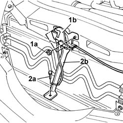
1. Undo the fixing nuts (1a) and remove the bonnet lock (1b) from the housing in the crossmember.
2. Undo the lower nut (2a) and remove the lock reinforcement bracket (2b).
1. Undo the retaining bolts.
2. Remove the upper front crossmember.
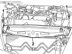
- Position a suitable container for collecting the engine coolant at the outlet of the upper pipe and the radiator.
1. Disconnect the upper radiator pipe.
- Remove the container for collecting the engine coolant and seal the housing in the radiator.
To disconnect the pipe, press the spring manually and release the rapid connector for the pipe from the retainer on the radiator.
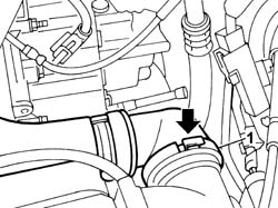
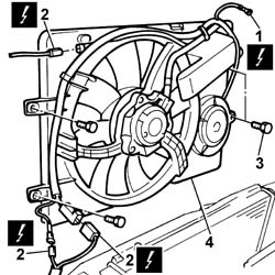
1. Undo the nut and disconnect the earth lead from the bodyshell.
| Description | Connector | |
|---|---|---|
| 1 | Right front earth | C011 |
2. Disconnect the electrical connections for the engine cables/fan-radiator cables coupling.
| Description | Connector | |
|---|---|---|
| 2 | Front/radiator coupling | D009A |
| Description | Connector | |
|---|---|---|
| 2 | Front/radiator coupling | D009B |
| Description | Connector | |
|---|---|---|
| 2 | Front/radiator coupling | D009C |
3. Undo the upper and lower bolts fixing the fan to the radiator assembly.
4. Remove the fan assembly from the upper part of the engine compartment.
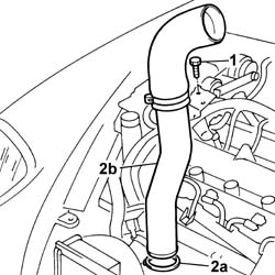
1. Undo the bolt fixing the rigid section of the inlet pipe to the air/air heat exchanger.
2. Disconnect the band (2a) and remove the rigid section of the air inlet pipe (2b) from the heat exchanger.
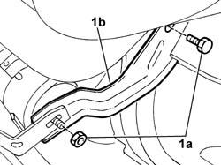
1. Undo the nut and the bolt (1a) and remove the mounting bracket (1b) for the engine oil heat exchanger pipes.
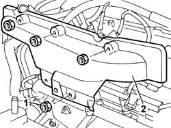
1. Undo the retaining nuts.
2. Remove the heat shield for the exhaust manifold.
- Raise the vehicle.
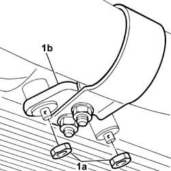
1. Undo the nuts (1a) fixing the mounting bracket (1b) for the front section of the exhaust pipe.
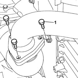
1. Undo the bolts fixing the front section of the exhaust pipe to the catalytic preconverter.
- Lower the front section of the exhaust pipe and move it aside.
- Keep the gasket for the front section of the exhaust pipe.
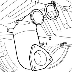
1. Loosen the nut fixing the collar joining the preconverter to the turbocharger.
2. Remove the catalytic preconverter.
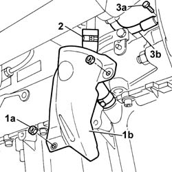
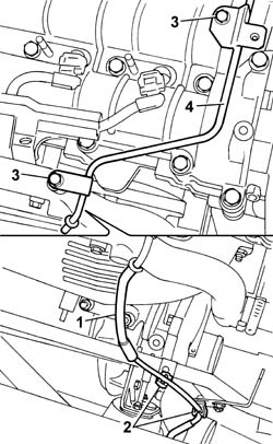
1. Undo the fixing nuts (1a) and remove the shield (1b).
2. Disconnect the flexible sump oil return pipe from the turbochager.
3. Undo the bolt (3a) and disconnect the turbocharger oil supply pipe (3b) from the cylinder block/crankcase.
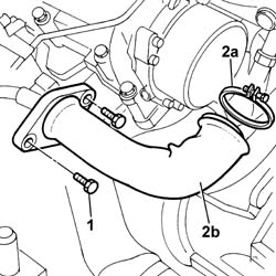
1. Undo the bolts fixing the E.G.R. system water/exhaust gas heat exchanger exhaust gas inlet pipe from the exhaust manifold.
2. Loosen the band (2a) and remove the E.G.R. system water/exhaust gas heat exchanger inlet pipe (2b).
- Keep the seals from the ends of the pipe.
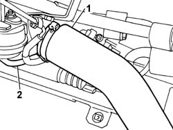
1. Disconnect the air pipe from the turbocharger.
2. Disconnect the vacuum pipe from the turbocharger.
1. Disconnect the flexible section of the vacuum pipe from the rigid section.
2. Release the flexible section from the mounting bands.
3. Undo the retaining bolts.
4. Release the rigid section of the vacuum pipe from the vacuum reservoir and move it away from the work area.
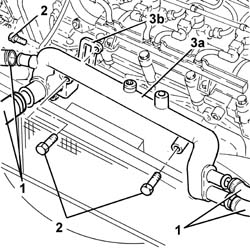
1. Disconnect the engine coolant pipes connected to the pump rigid water inlet pipe.
2. Undo the bolts securing the water inlet pipe to the pump.
3. Remove the pump rigid water inlet pipe (3a) and keep the gasket (3b) from underneath.
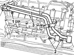
- Position a suitable container for collecting the engine coolant that comes out.
1. Undo the nuts fixing the oil pipes to the pump.
2. Undo the bolts fixing the join with the flexible oil return section from the heat exchanger.
3. Remove the two rigid engine oil pipes.
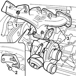
1. Undo the nuts securing the exhaust manifold to the cylinder head.
2. Undo the bolts fixing the reinforcement bracket to the cylinder head.
3. Remove the exhaust manifold / turbocharger assembly from the top.
- Keep the exhaust manifold gasket from underneath.
Refitting
- Fit the new exhaust manifold gasket in the special housing on the cylinder head.
- Fit the turbocharger-exhaust manifold assembly.
1. Tighten the self-locking nuts fixing the exhaust manifold to the cylinder head to torque.
| Value - daNm | Fastening | Component | Ø | |
|---|---|---|---|---|
| 1 | 2.5 | Nuts | EXHAUST MANIFOLD/S | M8 |
2. Tighten the reinforcement bracket fixing bolt to torque.
| Value - daNm | Fastening | Component | Ø | |
|---|---|---|---|---|
| 2 | 2.5 | Bolts | EXHAUST MANIFOLD RETAINING BRACKET | M8 |
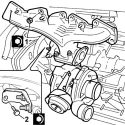
- Fit the two rigid engine oil pipes.
- Tighten the bolts fixing the join with the flexible oil return section from the heat exchanger to torque.
- Tighten the nuts fixing the oil pipes to the pump to torque.
- Fit the pump water inlet pipe together with a new gasket.
- Screw in the bolts fixing the pipe to the cylinder head and then tighten them to torque.
- Connect the engine coolant pipes using new bands.
- Place the rigid vacuum reservoir vacuum pipe in position and tighten the fixing bolts.
- Connect the flexible pipe to the rigid section of the pipe and secure the flexible section to the mounting bands.
- Connect the vacuum pipe from the variable geometry solenoid valve to the turbocharger and the air pipe to the air/air heat exchanger.
- Fit the E.G.R. system water/exhaust gas heat exchanger exhaust gas inlet pipe (1a) in place and tighten the securing band (1b).
- Tighten the bolts fixing the E.G.R. system water/exhaust gas heat exchanger exhaust gas inlet pipe to the exhaust manifold to the recommended torque.
- Tighten the connector fixing the oil delivery pipe to the turbocharger to the engine block.
- Connect the flexible sump oil return pipe to the turbochager.
- Fit the metal protection and tighten the two fixing nuts.
- Fit the catalytic preconverter in the housing on the turbocharger.
1. Tighten the nut fixing the collar joining the preconverter to the turbocharger to torque.
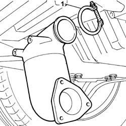
1. Join the flange for the front section of the exhaust pipe to the flange for the catalytic preconverter tightening the fixing bolts.
- It is advisable to fit a new gasket between the two flanges during this operation.
2. Tighten the fixing bolts to torque.
| Value - daNm | Fastening | Component | Ø | |
|---|---|---|---|---|
| (Preconverter) 2.8 | Bolts | EXHAUST PIPE TO ENGINE | M8 |
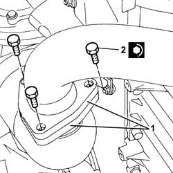
1. Tighten the nuts fixing the mounting bracket for the first section of the exhaust pipe to the oil sump to torque.
- Fit the heat shield in the housing in the exhaust manifold.
- Tighten the fixing nuts to torque.
- Fit the mounting bracket for the engine oil heat exchanger oil pipes and tighten the nut and the bolt to torque.
- Fit the rigid and flexible pipe assembly for the air inlet pipe to the air heat exchanger.
- Fasten the lower section using the band and the upper section of the pipe using the fixing bolt.
- Fit the fan assembly in the special housing.
- Tighten the upper and lower fixing bolts.
- Connect the electrical connections for the engine cables/fan-radiator cables coupling.
| Description | Connector | |
|---|---|---|
| Front/radiator coupling | D009A |
| Description | Connector | |
|---|---|---|
| Front/radiator coupling | D009B |
| Description | Connector | |
|---|---|---|
| Front/radiator coupling | D009C |
- Connect the earth lead to the bodyshell and secure it using the fixing nut.
| Description | Connector | |
|---|---|---|
| Right front earth | C011 |
- Connect the uppper engine coolant pipe to the radiator.
- Fit the upper front crossmember and tighten the fixing bolts to torque.
| Value - daNm | Fastening | Component | Ø | |
|---|---|---|---|---|
| 0.6 | Bolts | FRONT WING CROSSMEMBER HEADLAMP HOUSINGS | M6 |
- Fit the bonnet lid lock complete with bracket and tighten the nuts fixing it to the upper crossmember and to the lower crossmember.
See in Op. 1048A10 COMPLETE AIR FILTER -R.R.
See in Op. 1048A21 AIR INLET HOSE FROM INTAKE TO FILTER - R.R.
See in Op. 1048A50 air inlet pipe to turbocharger - r + r
See in Op. 1048A56 UPPER RESONATOR - R.R.
See in Op. 1048B44 RIGID air supply PIPE from heat exchanger to intake manifold - R.R.
See in Op. 1016A10 SOUND-PROOFING COVER - R.R.
See in Op. 7040D50 ENGINE COMPARTMENT UPPER SOUND INSULATION SHIELD - R.R.
See in Op. 7055B54 PROTECTION/GUARD under engine - R.R.
- Fill the engine cooling system as described in the operation:
See in Op. 0010T20 Engine REFRIGERANT FLUID - Change
- Top up or, if necessary, change the engine oil, referring to the following operation:
See in Op. 0010T10 ENGINE OIL - Change
- Or:
See in Op. 0010T11 ENGINE OIL - Check level and top up if necessary
- Remove the vehicle from the lift.
Parts & tools for this job Staging For 2002 Lancia Thesis
- PARTExhaust gasketSearch: Lancia Thesis 2002 exhaust gasket
- TOOLPenetrating oilSearch: penetrating oil
- TOOLOBD2 scannerSearch: OBD2 scanner
Links open Amazon search results in a new tab. As an Amazon Associate I earn from qualifying purchases.