
ENGINE - Position on stand and Remove
- Make
- Lancia
- Model
- Thesis Factory Service Manual
- Year
- 2002–2009
- Section
- Engine and power unit › ENGINE - Position on stand and Remove
ENGINE - Position on stand and Remove
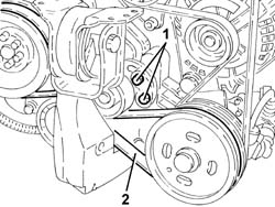
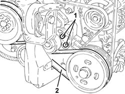
1. Loosen the bolts fixing the power assisted steering pump drive belt tensioner.
2. Release and remove the power assisted steering pump drive belt.
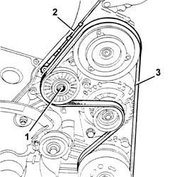
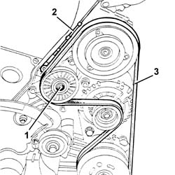
1. Loosen the bolt fixing the alternator/air conditioningn compressor drive belt tensioner.
2. Loosen the tension for the alternator/air conditioning compressor drive belt using the screw.
3. Release and remove the alternator/air conditioning compressor drive belt.
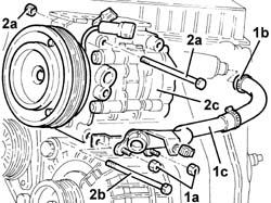
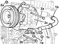
1. Undo the nuts (1a), loosen the band (1b) and remove the pipe (1c) between the supply pipe and the water pump rigid inlet pipe.
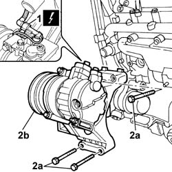
2. Undo the bolts (2a) and (2b) and remove the air conditioning compressor (2c).
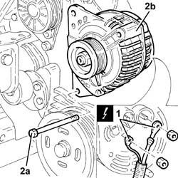
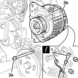
1. Disconnect the electrical connections from the alternator.
| Description | Connector | |
|---|---|---|
| 1 | Alternator | A010A |
2. Undo the bolts (2a) and remove the alternator (2b).
1. Release the electrical wiring from the band on the injection/ignition control unit mounting.
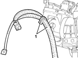
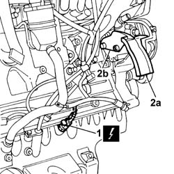
1. Disconnect the electrical connection from the insufficient engine oil pressure sensor.
| Description | Connector | |
|---|---|---|
| 1 | Insufficient engine oil pressure sensor | K030 |
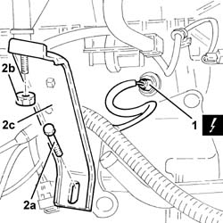
2. Undo the bolt (2a) and the nut (2b) and remove the modular intake manifold mounting bracket (2c).
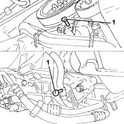
1. Undo the bolts fixing the supply/return pipes to the power assisted steering pump.
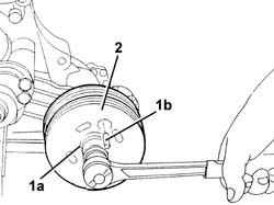
1. Undo the bolt (1a) fixing the power assisted steering pump using a suitable pin (1b) for counter-torque.
2. Remove the power assisted steering pump pulley.
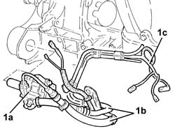
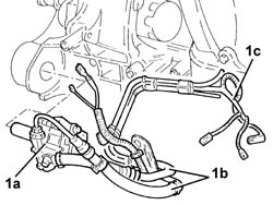
1. Release and remove the power assisted steering pump (1a) complete with pipes (1b) and electrical wiring (1c).
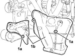
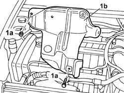
1. Undo the nuts (1a) and remove the exhaust manifold heat shields (1b).
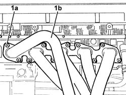
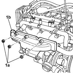
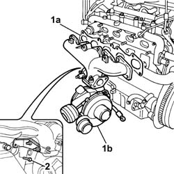
1. Undo the nuts (1a) and remove the exhaust manifold (1b) complete with gasket.
1. Undo the bolts fixing the alternator/air conditioning compressor drive belt tensioner to the timing side rigid engine support.
2. Undo the bolts (2a) and remove the timing side rigid engine support (2b).
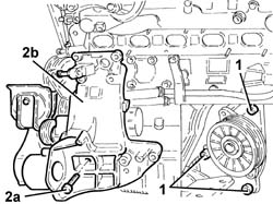
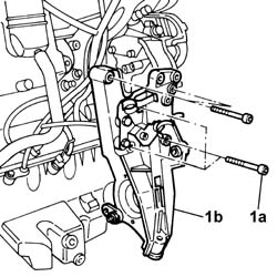
1. Undo the bolt connecting the intermediate driveshaft bearing support to the crankcase sump.
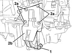
2. Undo the bolts (2a) and remove the intermediate driveshaft bearing support (2b).
- Undo the fastenings and remove the engine oil dipstick assembly.
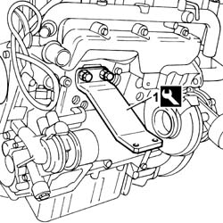
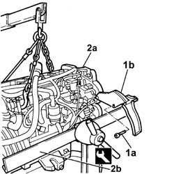
1. Fit the tool for positioning the engine on the overhaul stand.
| Description | Code | Function | |
|---|---|---|---|
| 1 | Brackets | 1.861.001.039 | Positioning engine on overhaul stand |
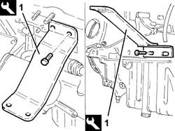
- Position the engine on the overhaul stand using a hydraulic hoist fitted with suitable chains.
- REMOVAL FROM THE STAND
- Remove the engine from the overhaul stand using a hydraulic hoist fitted with suitable chains.
- Remove the tool for positioning the engine on the overhaul stand.
| Description | Code | Function | |
|---|---|---|---|
| Brackets | 1.861.001.039 | Positioning engine on overhaul stand |
- Place the engine oil dipstick in its housing and secure it using the fastenings.
| Value - daNm | Fastening | Component | Ø | |
|---|---|---|---|---|
| 0,8 - 1,2 | OIL LEVEL DIPSTICK PIPE |
1. Place the intermediate driveshaft bearing support (1a) in its housing and secure it tightening the bolts (1b) to the recommended torque.
| Value - daNm | Fastening | Component | Ø | |
|---|---|---|---|---|
| 1b | 4.6 ÷ 6.6 | Bolt | FRONT DRIVE SHAFT BEARING MOUNT | M10 |
2. Tighten the bolt connecting the intermediate driveshaft bearing support to the crankcase sump.
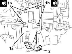
1. Place the timing side rigid engine support (1a) in its housing and secure it tightening the bolts (1b) to the recommended torque.
| Value - daNm | Fastening | Component | Ø | |
|---|---|---|---|---|
| 1b | (Timing side engine support side) 2.3 - 3.3 | Bolt | ALT./AUXILIARY DRIVEBELT MOBILE VARIOUS | M8 |
2. Tighten the bolts fixing the alternator/air conditioning compressor drive belt tensioner to the timing side rigid engine support.
| Value - daNm | Fastening | Component | Ø | |
|---|---|---|---|---|
| 2 | (Timing side engine support side) 2.3 - 3.3 | Bolt | ALT./AUXILIARY DRIVEBELT MOBILE VARIOUS | M8 |
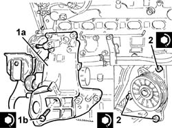
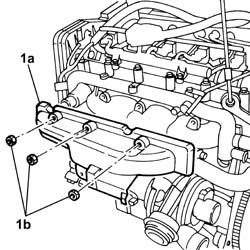
1. Place the exhaust manifold (1a), complete with gasket, back in its housing and secure it tightening the nuts (1b) to the recommended torque.
| Value - daNm | Fastening | Component | Ø | |
|---|---|---|---|---|
| 1b | 2.3 - 3.3 (cylinder head side) | Nut | EXHAUST MANIFOLD/S | M8 |
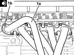
- Place the exhaust manifold heat shields in their housings and secure them using the nuts.
- Place the power assisted steering pump complete with pipes and electrical wiring in its housing.
1. Place the power assisted steering pump pulley (1a) in its housing and secure it tightening the bolt (1b) to the recommended torque using a suitable pin (1c) for counter-torque.
| Value - daNm | Fastening | Component | Ø | |
|---|---|---|---|---|
| 1b | 2.3 - 3.3 (power assisted steering pump side) | Bolt | POWER STEERING PUMP DRIVE PULLEY | M8 |
| Value - daNm | Fastening | Component | Ø | |
|---|---|---|---|---|
| (Power assisted steerign pump side) 9.2 - 13.3 | Nut | POWER STEERING PUMP DRIVE PULLEY | M16 |
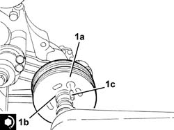
- Tighten the bolts fixing the supply/return pipes to the power assisted steering pump.
- Place the modular intake manifold mounting bracket in its housing and secure it using the nut and the bolt.
- Connect the electrical connection to the insufficient engine oil pressure sensor.
- Fasten the electrical wiring to the band on the injection/ignition control unit mounting.
1. Place the alternator (1a) in its housing and fasten it tightening the bolts (1b) to the recommended torque.
| Value - daNm | Fastening | Component | Ø | |
|---|---|---|---|---|
| 1b | 4.6 - 6.6 | Bolt | ALTERNATOR ASSEMBLY | M10 |
| Value - daNm | Fastening | Component | Ø | |
|---|---|---|---|---|
| 6.4 - 9.3 | Bolt | ALTERNATOR ASSEMBLY | M12 |
2. Connect the electrical connections to the alternator.
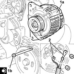
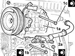
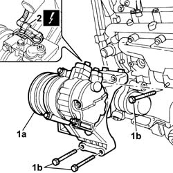
1. Place the air conditioning compressor (1a) in its housing and fasten it tightening the bolts (1b) and (1c) to the recommended torque.
| Value - daNm | Fastening | Component | Ø | |
|---|---|---|---|---|
| 1b | 2.3 - 3.3 (support side) | Bolt | COMPLETE AIR CONDITIONING COMPRESSOR | M8 |
| Value - daNm | Fastening | Component | Ø | |
|---|---|---|---|---|
| 1c | 2.3 - 3.3 (support side) | Bolt | COMPLETE AIR CONDITIONING COMPRESSOR | M8 |
2. Place the pipe (2a) from the supply pipe to the water pump rigid inlet pipe in its housing and secure it using the nuts (2b).
| Value - daNm | Fastening | Component | Ø | |
|---|---|---|---|---|
| 2b | 0.8 - 1.2 | Nuts | COOLANT PUMP RIGID INLET PIPE |
1. Fit the alternator/air conditioning compressor drive belt.
2. Tension the alternator/air conditioning compressor drive belt using the screw.
- Using the C.TRONIC G2 105.5 equipment or similar, check that the alternator/air conditioning compressor drive belt tension corresponds to the recommended figures.
| Subject | Value | |
|---|---|---|
| Alternator/air conditioning compressor drive belt | daNm | |
| Tension | 63 - 80 |
- If the tension does not correspond to the recommended figures, regulate the adjustment screw.
3. Tighten the bolt fixing the alternator/air conditioning compressor drive belt tensioner.
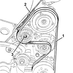
1. Fit the power assisted steering pump drive belt.
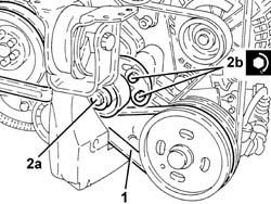
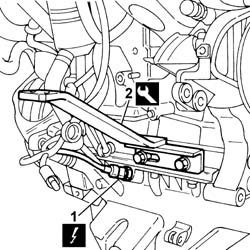
2. Tension the power assisted steering pump drive belt using a polygonal spanner on the tensioner screw (2a), then tighten the bolts (2b) to the recommended torque.
| Value - daNm | Fastening | Component | Ø | |
|---|---|---|---|---|
| 2b | (Timing side rigid power unit support) 2.3 ÷ 3.3 | Bolt | ALT./AUXILIARY DRIVEBELT POWER ASSISTED STEERING PUMP | M8 |
- Using the tool, check that the power assisted steering pump belt tension corresponds to the recommended figures.
| Description | Code | Function | |
|---|---|---|---|
| Torque wrench | 1.895.762.000 | Power steering pump drive belt tensioning |
| Subject | Value | |
|---|---|---|
| Power assisted steering pump drive belt | daNm | |
| Tension | 45 - 62 |
- If the tension does not correspond to the recommended figures, repeat the above operations.
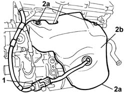
1. Disconnect the electrical connection for the left head Lambda sensor
| Description | Connector | |
|---|---|---|
| 1 | Lambda sensor on pre-catalyzer | K015 |
2. Undo the three nuts (2a) fixing the left pre-converter heat shield (2b) and remove it
1. Undo the bolt (1a) fixing the engine oil dipstick pipe (1b) to the left head, then undo the connector (1c) on the crankcase and remove the pipe
- Undo the nuts fixing the left pre-catalyzer and remove it
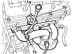
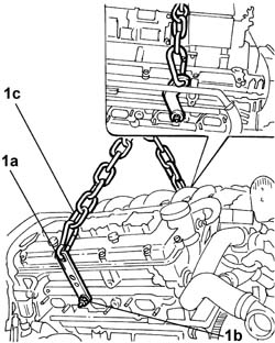
1. Positino the two mounting brackets (1a) securing them to the studs (1b) for the exhaust manifolds and secure the engine using a suitable hoisting system (1c).
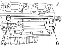
1. Undo the bolt fixing the reinforcement bracket (1a), then undo the connector (1b) for the gearbox oil/water heat exchanger rigid coolant supply pipe and remove the pipe.
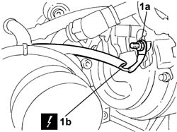
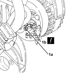
1. Undo the fixing nut (1a) and disconnect the energizing cable (1b) from the alternator.
| Description | Connector | |
|---|---|---|
| 1b | Alternator | A010A |
| Description | Connector | |
|---|---|---|
| 1b | Alternator | A010B |
1. Disconnect the electrical connector for the insufficient oil pressure sensor.
| Description | Connector | |
|---|---|---|
| 1 | Insufficient engine oil pressure sensor | K030 |
2. Remove the oil filter cartridge using a suitable tool.
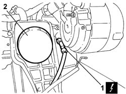
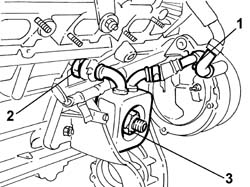
1. Undo the bolt fixing the coolant connectors on the alternator and disconnect the connectors.
2. Open the band retaining the pipe from the crankcase to the engine oil/water heat exchanger and disconnect the pipe from the heat exchanger.
3. Undo the centre nut fixing the engine oil/water heat exchanger and remove the heat exchanger
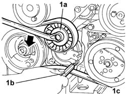
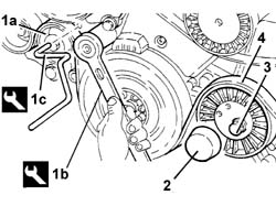
1. Using a spanner as illustrated in the diagram, move the moving tensioner (1a) for the auxiliary shaft drive belt and fit a 4 mm diameter pin (1b) to keep the tensioner in position, then remove the belt (1c).
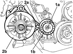
1. Undo the bolt (1a) fixing the fixed tensioner (1b) and remove it.
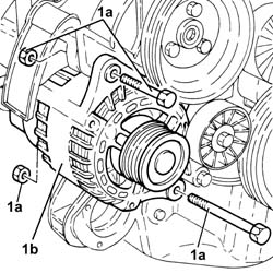
2. Undo the two bolts (2a) fixing the alternator (2b) and remove it.
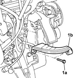
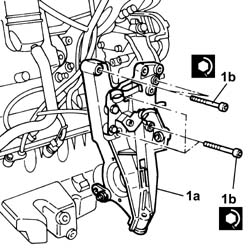
1. Undo the fastenings (1a) and remove the rear engine support (1b).
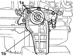
1. Remove the gasket under the support.
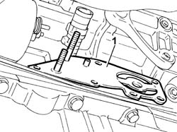
1. Disconnect the connection for the air conditioning compressor electro-magnet coupling wiring.
| Description | Connector | |
|---|---|---|
| 1 | Air conditioning compressor engagement electro-magnet | L020 |
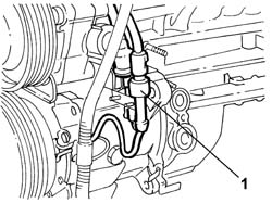
1. Undo the two fastenings (1a) for the air conditioning system compressor (1b) and remove it
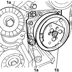
1. Position the mounting brackets (1a) and secure the engine to the stand (1b), then remove the hoists and support.
| Description | Code | Function | |
|---|---|---|---|
| 1a | Engine mounting brackets | 1.861.001.038 | Engine fastening to support stand |
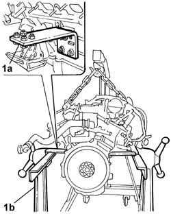
- Proceed with the removal of the engine from the stand, following the instructions given below:
- Position suitable hoisting and support systems, then release it from the rotating stand and remove the mounting brackets
- Position the air conditioning system compressor and tighten the two fixing bolts to the recommended torque.
| Value - daNm | Fastening | Component | Ø | |
|---|---|---|---|---|
| 5 | Bolt | AIR CONDITIONER ASSEMBLY COMPRESSOR | M10 X 1.25 |
- Connect the connection for the air conditioning compressor electro-magnet coupling wiring.
| Description | Connector | |
|---|---|---|
| Air conditioning compressor engagement electro-magnet | L020 |
- Position the gasket under the rear engine support.
- Position the rear engine support and tighten the fastenings to the crankcase to the recommended torque.
| Value - daNm | Fastening | Component | Ø | |
|---|---|---|---|---|
| (to the cylinder block/crankcase) 2 | Bolt | RIGID REAR SUPPORT POWER UNIT | M8 |
- Position the alternator and tighten the two fixing bolts.
| Value - daNm | Fastening | Component | Ø | |
|---|---|---|---|---|
| 6,7 | Bolt | ALTERNATOR ASSEMBLY | M10 |
| Value - daNm | Fastening | Component | Ø | |
|---|---|---|---|---|
| 8,6 | Bolt | ALTERNATOR ASSEMBLY | M12 |
- Position the single drive belt fixed tensioner and tighten the fixing bolt.
| Value - daNm | Fastening | Component | Ø | |
|---|---|---|---|---|
| 2.2 | Bolt | SINGLE BELT MOVING TENSIONER VARIOUS | M8 |
- Fit the belt and remove the moving tensioner retaining pin.
- Position the engine oil heat exchanger and tighten the centre fixing nut to the recommended torque.
| Value - daNm | Fastening | Component | Ø | |
|---|---|---|---|---|
| 3 | Connector | ENGINE OIL HEAT EXCHANGER | M18 X 1,5 |
- Connect the pipe between the heat exchanger and the cylinder block/crankcase and secure the retaining band.
- Secure the connectors, complete with gaskets, on the alternator using the fixing bolt.
Always replace the seals on the alternator cooling pipe connectors.
- Position the oil filter, tightening it manually
- Connect the electrical connector for the insufficient oil pressure sensor.
- Position the alternator energizing cable and tighten the fixing nut.
| Value - daNm | Fastening | Component | Ø | |
|---|---|---|---|---|
| 0.5 | Nut | ALTERNATOR | M8 |
- Position the rigid pipe and copper washers and partly tighten the connector securing them to the crankcase.
- Tighten the bolt fixing the gearbox oil/water heat exchanger rigid coolant supply pipe support plate to the recommended torque.
| Value - daNm | Fastening | Component | Ø | |
|---|---|---|---|---|
| 1.5 | Bolt | PIPE TO CYLINDER BLOCK/CRANKCASE FIXING, BOLT | M8 |
- Tighten the connector fixing the pipe to the cylinder block/crankcase to the recommended torque.
| Value - daNm | Fastening | Component | Ø | |
|---|---|---|---|---|
| 4 | Connector | CRANKCASE RIGID WATER RETURN PIPE | M16 X 1.5 |
- Connect the flexible and rigid pipes and close the band.
- Remove the engine mounting brackets.
- Position the pre-catalyzer and gasket and tighten the fixing nuts to the recommended torque.
| Value - daNm | Fastening | Component | Ø | |
|---|---|---|---|---|
| 2,7 | Nut | EXHAUST MANIFOLD/S | M8 |
- Position the oil dipstick pipe tightening the connector fixing it to the cylinder block/crankcase to the recommended torque.
| Value - daNm | Fastening | Component | Ø | |
|---|---|---|---|---|
| 8 | Connector | OIL LEVEL DIPSTICK PIPE | M14 X 1.5 |
- Tighten the bolt fixing the oil dipstick pipe to the left head to the recommended torque.
| Value - daNm | Fastening | Component | Ø | |
|---|---|---|---|---|
| 2,5 | Bolt | OIL LEVEL DIPSTICK PIPE | M16 X 1.5 |
- Position the heat shield and tighten the three fixing nuts.
- Connect the electrical connection for the left head Lambda sensor
| Description | Connector | |
|---|---|---|
| Lambda sensor on pre-catalyzer | K015 |
1. Loosen the bolts fixing the power assisted steering pump drive belt tensioner, where fitted.
2. Release and remove the power assisted steering pump drive belt.
1. Loosen the bolt fixing the alternator/air conditioningn compressor drive belt tensioner.
2. Loosen the tension for the alternator/air conditioning compressor drive belt using the screw.
3. Release and remove the alternator/air conditioning compressor drive belt.
1. Undo the nuts (1a), loosen the band (1b) and remove the pipe (1c) between the supply pipe and the water pump rigid inlet pipe.
2. Undo the bolts (2a) and (2b) and remove the air conditioning compressor (2c).
1. Disconnect the electrical connections from the alternator.
| Description | Connector | |
|---|---|---|
| 1 | Alternator | A010A |
2. Undo the bolts (2a) and remove the alternator (2b).
1. Release the electrical wiring from the band on the injection/ignition control unit mounting.
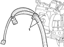
1. Undo the fixing bolts (1a) and nuts (1b) and disconnect the earth lead (1c).
| Description | Connector | |
|---|---|---|
| 1c | Earth on engine | C040 |
- Lower the lift.
2. Release the wiring from the springs and remove the chamber mounting bracket.
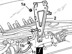
1. Undo the bolts fixing the supply/return pipes to the power assisted steering pump.
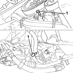
1. Undo the bolt (1a) fixing the power assisted steering pump using a suitable pin (1b) for counter-torque.
2. Remove the power assisted steering pump pulley.
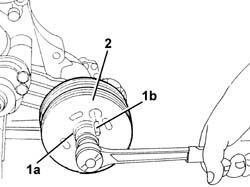
1. Release and remove the power assisted steering pump (1a) complete with pipes (1b) and electrical wiring (1c).
1. Undo the bolts (1a) and remove the exhaust manifold heat shields (1b).
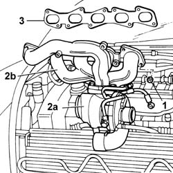
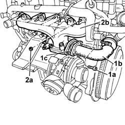
1. Undo the nuts securing the exhaust manifold to the cylinder head.
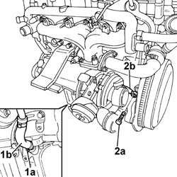
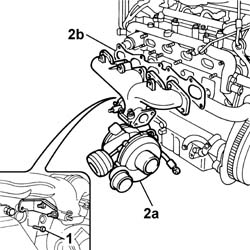
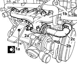
2. Remove the turbocharger (2a) complete with exhaust manifold (2b).
3. Remove the exhaust manifold gasket from the studs on the cylinder head.
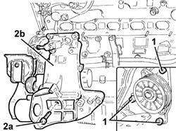
1. Undo the bolts fixing the alternator/air conditioning compressor drive belt tensioner to the timing side rigid engine support.
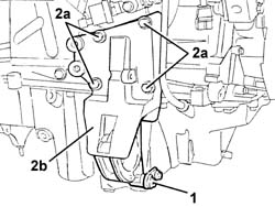
2. Undo the bolts (2a) and remove the exhaust side rigid engine support assembly (2b).
1. Undo the bolt connecting the intermediate driveshaft bearing support to the crankcase sump.
2. Undo the bolts (2a) and remove the intermediate driveshaft bearing support (2b).
- Undo the fastenings and remove the engine oil dipstick assembly.
1. Fit the tool for positioning the engine on the overhaul stand.
| Description | Code | Function | |
|---|---|---|---|
| 1 | Brackets | 1.861.001.039 | Brackets for securing engine to universal stand |
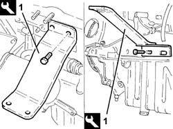
- Position the engine on the overhaul stand using a hydraulic hoist fitted with suitable chains.
- REMOVAL FROM THE STAND.
- Remove the engine from the overhaul stand using a hydraulic hoist fitted with suitable chains.
- Remove the tool for positioning the engine on the overhaul stand.
| Description | Code | Function | |
|---|---|---|---|
| 1 | Brackets | 1.861.001.039 | Brackets for securing engine to universal stand |
- Place the engine oil dipstick in its housing and secure it using the fastenings.
1. Place the intermediate driveshaft bearing support (1a) in its housing and secure it tightening the bolts (1b) to the recommended torque.
| Value - daNm | Fastening | Component | Ø | |
|---|---|---|---|---|
| 1b | 4.6 ÷ 6.6 | Bolt | FRONT DRIVE SHAFT BEARING MOUNT | M10 |
2. Tighten the bolt connecting the intermediate driveshaft bearing support to the crankcase sump.
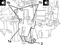
1. Place the exhaust side rigid engine support (1a) in its housing and secure it tightening the bolts (1b) to the recommended torque.
| Value - daNm | Fastening | Component | Ø | |
|---|---|---|---|---|
| 1b | 4.6 - 6.6 (crankcase side) | Bolt | RIGID ENGINE SUPPORT, TIMING SIDE | M10 |
2. Tighten the bolts fixing the alternator/air conditioning compressor drive belt tensioner to the exhaust side rigid engine support.
| Value - daNm | Fastening | Component | Ø | |
|---|---|---|---|---|
| 2 | (Timing side engine support side) 2.3 - 3.3 | Bolt | ALT./AUXILIARY DRIVEBELT MOBILE VARIOUS | M8 |
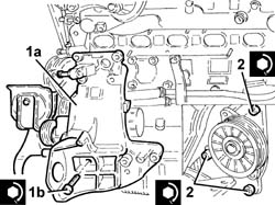
1. Place the exhaust manifold (1a), complete with gasket, back in its housing and secure it tightening the nuts (1b) to the recommended torque.
| Value - daNm | Fastening | Component | Ø | |
|---|---|---|---|---|
| 1b | 2.3 - 3.3 (cylinder head side) | Nut | EXHAUST MANIFOLD/S | M8 |
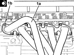
- Place the exhaust manifold heat shields in their housings and secure them using the nuts.
- Place the power assisted steering pump complete with pipes and electrical wiring in its housing.
1. Place the power assisted steering pump pulley (1a) in its housing and secure it tightening the bolt (1b) to the recommended torque using a suitable pin (1c) for counter-torque.
| Value - daNm | Fastening | Component | Ø | |
|---|---|---|---|---|
| 1b | 2.3 - 3.3 (power assisted steering pump side) | Bolt | POWER STEERING PUMP DRIVE PULLEY | M8 |
| Value - daNm | Fastening | Component | Ø | |
|---|---|---|---|---|
| (Power assisted steerign pump side) 9.2 - 13.3 | Nut | POWER STEERING PUMP DRIVE PULLEY | M16 |
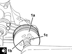
- Tighten the bolts fixing the supply/return pipes to the power assisted steering pump.
- Place the modular intake manifold mounting bracket in its housing and secure it using the nut and the bolt.
- Connect the electrical connection to the insufficient engine oil pressure sensor.
- Fasten the electrical wiring to the band on the injection/ignition control unit mounting.
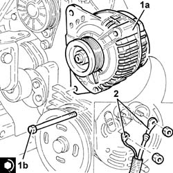
1. Place the alternator (1a) in its housing and fasten it tightening the bolts (1b) to the recommended torque.
| Value - daNm | Fastening | Component | Ø | |
|---|---|---|---|---|
| 1b | 4.6 - 6.6 | Bolt | ALTERNATOR ASSEMBLY | M10 |
2. Connect the electrical connections to the alternator.
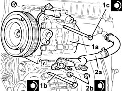
1. Place the air conditioning compressor (1a) in its housing and fasten it tightening the bolts (1b) and (1c) to the recommended torque.
| Value - daNm | Fastening | Component | Ø | |
|---|---|---|---|---|
| 1b | 4.6 ÷ 6.6 | Bolt | COMPLETE AIR CONDITIONING COMPRESSOR | M10 |
2. Place the pipe (2a) from the supply pipe to the water pump rigid inlet pipe in its housing and secure it using the nuts (2b).
1. Fit the alternator/air conditioning compressor drive belt.
2. Tension the alternator/air conditioning compressor drive belt using the special screw. Tension the alternator/air conditioning compressor drive belt using the special screw.
- Using the C.TRONIC G2 105.5 equipment or similar, check that the alternator/air conditioning compressor drive belt tension corresponds to the recommended figures.
| Subject | Value | |
|---|---|---|
| Alternator/air conditioning compressor drive belt | Nm | |
| Tension | 63 - 80 |
- If the tension does not correspond to the recommended figures, regulate the adjustment screw.
3. Tighten the bolt fixing the alternator/air conditioning compressor drive belt tensioner.
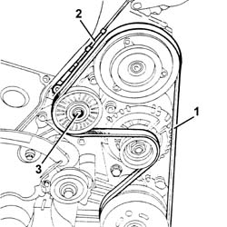
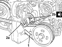
1. Fit the power assisted steering pump drive belt.
2. Tension the power assisted steering pump drive belt using a polygonal spanner on the tensioner screw (2a), then tighten the bolts (2b) to the recommended torque.
| Value - daNm | Fastening | Component | Ø | |
|---|---|---|---|---|
| 2b | 4.6 - 6.6 (Timing side rigid power unit support) | Bolt | MOVING TENSIONER FOR POWER ASSISTED STEERING PUMP DRIVE BELT | M8 |
- Using the tool, check that the power assisted steering pump belt tension corresponds to the recommended figures.
| Description | Code | Function | |
|---|---|---|---|
| Tension | 1.895.762.000 | Power steering pump drive belt tensioning |
| Subject | Value | |
|---|---|---|
| Power assisted steering pump drive belt | Nm | |
| Tension | 45 - 62 |
- If the tension does not correspond to the recommended figures, repeat the above operations.
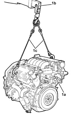
1. Secure and support the engine (1a) using a hydraulic lift (1b) fitted with suitable chains (1c).
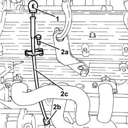
1. Release the engine oil dipstick and remove it.
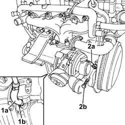
2. Undo the fixing bolt (2a) and the connector (2b), then remove the engine oil dipstick pipe (2c).
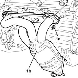
1. Undo the nuts (1a) and remove the left exhaust manifold with built in catalytic converter (1b).
2. Remove the seals.
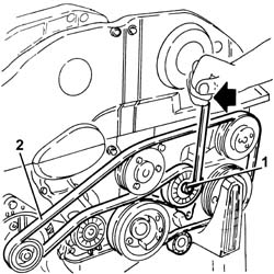
1. Use a spanner on the engine components single belt moving tensioner to loosen the belt tension.
2. Remove the single engine components drive belt.
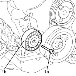
1. Undo the bolt (1a) and remove the engine components single belt fixed tensioner (1b).
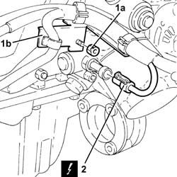
1. Undo the nut (1a) fixing the electric wiring mounting bracket (1b).
2. Disconnect the electrical connection from the insufficient engine oil pressure sensor.
| Description | Connector | |
|---|---|---|
| 2 | Insufficient engine oil pressure sensor | K030 |
1. Undo the bolts (1a) and remove the alternator (1b) complete with electrical wiring (1c).
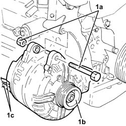
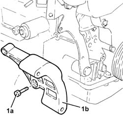
1. Undo the bolts (1a) and remove the alternator mounting (1b).
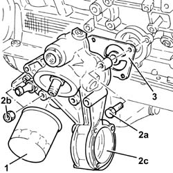
1. Remove the engine oil filter using a suitable tool.
2. Undo the bolts (2a) and the nuts (2b) and remove the engine oil filter/intermediate driveshaft mounting (2c).
3. Remove the seal.
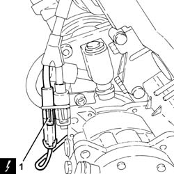
1. Disconnect the electrical connection for the air conditioning compressor electro-magnet coupling.
| Description | Connector | |
|---|---|---|
| 1 | Air conditioning compressor engagement electro-magnet | L020 |
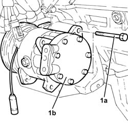
1. Undo the bolts (1a) and remove the air conditioner compressor (1b).
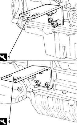
1. Fit the brackets for supporting the engine on the overhaul stand.
| Description | Code | Function | |
|---|---|---|---|
| 1 | Brackets | 1.820.145.000 | Fitting engine on overhaul stand |
- Position the engine on the overhaul stand using the special brackets, then release it from the hydraulic lift.
- Secure and support the engine using a hydraulic lift fitted with chains.
- Undo the fastenings and remove the engine complete with mounting brackets from the overhaul stand.
- Undo the fastenings and remove the mounting brackets from the engine and put them down.
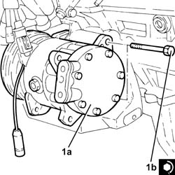
1. Place the air conditioning compressor (1a) in its housing and fasten it tightening the bolts (1b) to the recommended torque.
| Value - daNm | Fastening | Component | Ø | |
|---|---|---|---|---|
| 1b | (Mount side) 4.5 - 5.5 | Bolt | COMPLETE AIR CONDITIONING COMPRESSOR | M10 |
- Connect the electrical connection for the air conditioning compressor electro-magnet coupling.
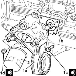
1. Place the engine oil filter mounting/intermediate driveshaft (1a) in position complete with gasket and secure it tightening the bolts (1c) and the nuts (1d) to the recommended torque.
| Value - daNm | Fastening | Component | Ø | |
|---|---|---|---|---|
| 1c | (Engine crankcase side) 2.3 - 2.8 | Bolt | OIL FILTER MOUNTING/FRONT DRIVESHAFT BEARING FRONT | M8 |
| Value - daNm | Fastening | Component | Ø | |
|---|---|---|---|---|
| 1d | (Engine crankcase side) 2.3 - 2.8 | Nut | OIL FILTER MOUNTING/FRONT DRIVESHAFT BEARING FRONT | M8 |
2. Fit the engine oil filter and tighten it fully by hand.
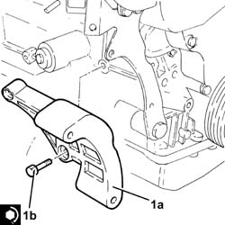
1. Place the alternator mounting (1a) in its housing and secure it tightening the bolts (1b) to the recommended torque.
| Value - daNm | Fastening | Component | Ø | |
|---|---|---|---|---|
| 1b | (Engine crankcase side) 1.9 - 2.3 | Bolt | ALTERNATOR SUPPORT | M8 |
| Value - daNm | Fastening | Component | Ø | |
|---|---|---|---|---|
| 1b | (Engine crankcase side) 4.3 - 5.3 | Bolt | ALTERNATOR SUPPORT | M10 |
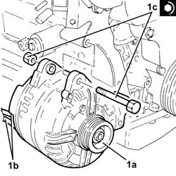
1. Place the alternator (1a) in its housing complete with electrical wiring (1b) and fasten it tightening the bolts (1b) to the recommended torque.
| Value - daNm | Fastening | Component | Ø | |
|---|---|---|---|---|
| (Mount side) 2.3 - 2.8 | Bolt | ALTERNATOR ASSEMBLY | M8 |
- Connect the electrical connection to the insufficient engine oil pressure sensor.
- Tighten the nut fixing the electric wiring mounting bracket.
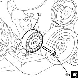
1. Position the engine components single belt fixed tensioner (1a) in its housing and secure it tightening the bolt (1b) to the recommended torque.
| Value - daNm | Fastening | Component | Ø | |
|---|---|---|---|---|
| 1b | 2.3 ÷ 2.8 | Bolt | SINGLE BELT FIXED TENSIONER VARIOUS | M8 |
- Place the engine components single belt in its housing keeping the moving tensioner in a slack position using a suitable spanner.
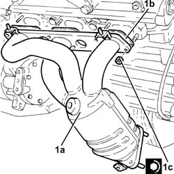
1. Place the left exhaust manifold with built in catalytic preconverter (1a), back in its housing complete with gaskets (1b) and secure it tightening the nuts (1c) to the recommended torque.
| Value - daNm | Fastening | Component | Ø | |
|---|---|---|---|---|
| 1c | (Cylinder head side) 2.4 - 3.0 | Nut | EXHAUST MANIFOLD/S | M8 |
- Place the engine oil dipstick pipe back in its housing and fasten it with the connector and the bolt.
- Place the engine oil dipstick back in its housing.
- Release the engine from the hydraulic lift.
- Operation not available.
| Description | Code | Function | |
|---|---|---|---|
| 1b | Spanner | 1.860.966.000 | Tensioning auxiliary shaft belt |
| Description | Code | Function | |
|---|---|---|---|
| 1c | Lock | 1.870.645.000 | Tensioning auxiliary shaft belt |
| Description | Connector | |
|---|---|---|
| 1b | Alternator | A010A |
| Description | Connector | |
|---|---|---|
| 1b | Alternator | A010B |
| Description | Connector | |
|---|---|---|
| 1 | Engine oil level sensor | K032 |
| Description | Code | Function | |
|---|---|---|---|
| 2 | Brackets | 1.861.001.039 | Engine support on overhaul stand |
| Description | Connector | |
|---|---|---|
| 1 | Air conditioning compressor engagement electro-magnet | L020 |
| Description | Code | Function | |
|---|---|---|---|
| 1 | Brackets | 1.861.001.039 | Engine support on overhaul stand |
| Description | Code | Function | |
|---|---|---|---|
| 2b | Overhaul stand | 1.861.000.000 | Support the engine |
| Description | Code | Function | |
|---|---|---|---|
| Overhaul stand | 1.871.001.000 | Support the engine |
| Description | Code | Function | |
|---|---|---|---|
| Brackets | 1.861.001.039 | Engine support on overhaul stand |
| Value - daNm | Fastening | Component | Ø | |
|---|---|---|---|---|
| 1a | 2.5 | Nut | EXHAUST MANIFOLD/S | M8 |
| Description | Connector | |
|---|---|---|
| 2 | Air conditioning compressor engagement electro-magnet | L020 |
| Description | Connector | |
|---|---|---|
| 1 | Engine oil level sensor | K032 |
| Value - daNm | Fastening | Component | Ø | |
|---|---|---|---|---|
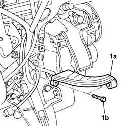
| 1b | 5 | Bolt | RIGID REAR SUPPORT POWER UNIT | M10 X 1.25 |
| Value - daNm | Fastening | Component | Ø | |
|---|---|---|---|---|
| 1b | 2.5 | Bolt | RIGID REAR SUPPORT POWER UNIT | M8 |
| Value - daNm | Fastening | Component | Ø | |
|---|---|---|---|---|
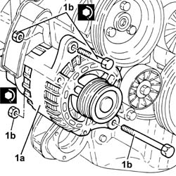
| 1b | 5 | Nut | ALTERNATOR ASSEMBLY | M10 X 1.25 |
| Value - daNm | Fastening | Component | Ø | |
|---|---|---|---|---|
| 1b | 7 | Nut | ALTERNATOR ASSEMBLY | M12 X 1.25 |
| Description | Connector | |
|---|---|---|
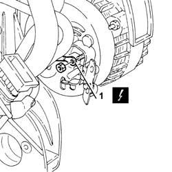
| 1 | Alternator | A010A |
| Description | Connector | |
|---|---|---|
| 1 | Alternator | A010B |
Parts & tools for this job Staging For 2002 Lancia Thesis
- PARTEngine gasket setSearch: Lancia Thesis 2002 engine gasket set
- TOOLTorque wrenchSearch: 3/8 inch torque wrench
- TOOLFeeler gauge setSearch: feeler gauge set
Links open Amazon search results in a new tab. As an Amazon Associate I earn from qualifying purchases.