
Junction UNIT - R.R.
- Make
- Lancia
- Model
- Thesis Factory Service Manual
- Year
- 2002–2009
- Section
- Instrument/gauge electrical circuits › Junction UNIT - R.R.
Junction UNIT - R.R.
Removing
- Disconnect the negative battery terminal.
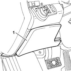
1. Remove the fuse access cover.
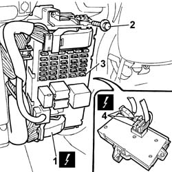
1. Disconnect the front electrical connectors for the junction unti complete with body computer.
2. Undo the fixing bolts.
3. Remove the junction unit complete with body computer from the housing.
| Description | Connector | |
|---|---|---|
| 1 | Junction unit under dashboard | B002A |
| Description | Connector | |
|---|---|---|
| 1 | Junction unit under dashboard | B002B |
| Description | Connector | |
|---|---|---|
| 1 | Junction unit under dashboard | B002D |
4. Disconnect the rear electrical connectors for the junction unti complete with body computer.
| Description | Connector | |
|---|---|---|
| 4 | Junction unit under dashboard | B002F |
| Description | Connector | |
|---|---|---|
| 4 | Junction unit under dashboard | B002G |
| Description | Connector | |
|---|---|---|
| 4 | Junction unit under dashboard | B002H |
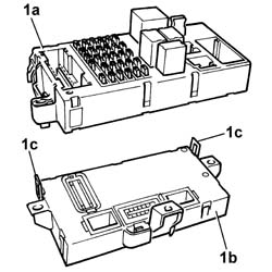
1. At the bench, separate the junction unit (1a) from the body computer (1b) acting on the retaining springs (1c).
Refitting
- Assemble the junction unit and the body computer, until the click of the retaining springs is heard.
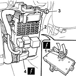
1. Connect the rear electrical connectors for the junction unti complete with body computer.
| Description | Connector | |
|---|---|---|
| 1 | Junction unit under dashboard | B002F |
| Description | Connector | |
|---|---|---|
| 1 | Junction unit under dashboard | B002G |
| Description | Connector | |
|---|---|---|
| 1 | Junction unit under dashboard | B002H |
2. Fit the junction unit complete with body computer in the housing.
3. Tighten the fixing bolts.
4. Connect the front electrical connectors for the junction unti complete with body computer.
| Description | Connector | |
|---|---|---|
| 4 | Junction unit under dashboard | B002A |
| Description | Connector | |
|---|---|---|
| 4 | Junction unit under dashboard | B002B |
| Description | Connector | |
|---|---|---|
| 4 | Junction unit under dashboard | B002D |
- Fit the fuse access cover.
- Connect the negative battery terminal.
Parts & tools for this job Staging For 2002 Lancia Thesis
- TOOLDigital multimeterSearch: automotive digital multimeter
- PARTAssorted fuse kitSearch: car fuse assortment kit
- TOOLWire crimper and connector kitSearch: wire crimper connector kit
Links open Amazon search results in a new tab. As an Amazon Associate I earn from qualifying purchases.