
Gear engagement cable - r r
- Make
- Fiat
- Model
- Ulysse Factory Service Manual
- Year
- 2002–2010
- Section
- Manual gearbox external controls › Gear engagement cable - r r
GEAR ENGAGEMENT CABLE - R R
Removing
Op. 5530B56 BATTERY DRIP TRAY COVER - R.R.
- Disconnect the negative battery terminal.
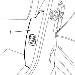
1. Release the pillar cover using a suitable tool and remove it.
Op. 7040A68 GRILLE FOR CENTRE DASHBOARD SPEAKER - R.R.
- < R1 > [All]
Op. 7040A45 FACIA RH SIDE COVER - R R
Op. 7040G22 FACIA COMPARTMENT LIGHT SWITCH/BULB HOLDER - R+R
Op. 7040A31 FLAP ASSEMBLY - R R
Op. 7040A44 SEAT INTERIOR GUARD - R R
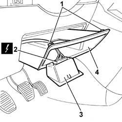
1. Act on the springs and partly extract the glove compartment housing from the trim under the dashboard.
2. Disconnect the diagnostic socket electrical connection.
3. Remove the connector holder trim complete with diagnostic socket.
4. Remove the glove compartment housing.
Op. 7040A60 UNDER FACIA TRIM - R+R
Op. 7040A65 PASSENGER COMPARTMENT BOX LOCK, ONE, R R
- < R1 > [Both]
Op. 2125C24 GEAR LEVER KNOB - R + R
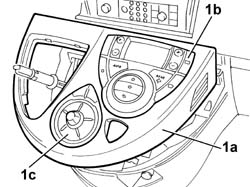
- Using a suitable tool, release the connect and climate control system control unit holder surround.
- Disconnect the electrical connections for the climate control system control unit.
1. Remove the surround (1a) complete with climate control system control unit (1b) and connect functions control unit (1c).
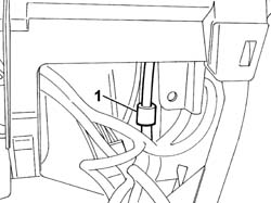
1. Disconnect the cooling hose.
- Extract the hazard warning lights switch.
- Disconnect the electrical connection.
1. Remove the hazard warning lights switch.
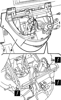
2. Undo the retaining bolts.
- Partly extract the centre console.
3. Disconnect the electrical connections (3a), (3b) and (3c).
4. Remove the console.
- Remove the passenger compartment temperature sensor
Op. 5010B18 CLIMATE CONTROL UNIT AIR INTAKE - R.R.
See in Op. 1048A10
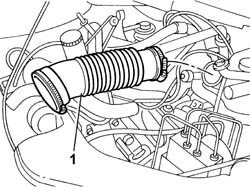
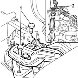
1. Undo the bolts fixing the gearbox linkage mounting.
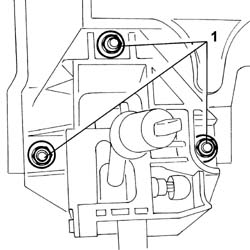
1. Move the rubber shield away from the work area.
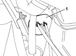
1. Undo the bolts fixing the selector unit to the gearbox.
2. Disconnect the gear selector and engagement flexible rod ends from the selector unit.
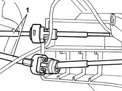
- Join the gear engagement flexible rods to a sensor so that the engagement of the gear selector and engagement flexible rods is faciliated during the refitting stage.
1. Remove the gear engagement flexible rods from the passenger compartment without disconnect the reverse inhibitor.
Refitting
- Posiion the gear engagement flexible roads working via the passenger compartment.
- Tighten the bolts fixing the selector unit to the gearbox.
- Working via the engine compartment, pull the sensor and position the rapid connectors for the gear engagement flexible rods on the selector unit.
- Fasten the ends of the gear engagement flexible rods to the selector unit.
- Position the rubber retainer.
- Tighten the bolts fixing the gearbox linkage mounting.
See in Op. 1048A10
Op. 5010B18 CLIMATE CONTROL UNIT AIR INTAKE - R.R.
- Position the passenger compartment temperature sensor
- Connect the electrical connections.
- Place the centre console in position and tighten the fixing bolts.
- Connect the electrical connection.
- Place the hazard warning lights switch in position.
- Connect the electrical connections for the climate control system control unit.
- Connect the cooling hose.
- Position the surround complete with climate control system control unit and connect functions control unit.
Op. 2125C24 GEAR LEVER KNOB - R + R
Op. 7040A65 PASSENGER COMPARTMENT BOX LOCK, ONE, R R
Op. 7040A60 UNDER FACIA TRIM - R+R
- Position the surround and place it in the glove compartment.
- Connect the electrical connection.
- Position the glove compartment in the trim under the dashboard.
Op. 7040A44 SEAT INTERIOR GUARD - R R
Op. 7040A31 FLAP ASSEMBLY - R R
Op. 7040G22 FACIA COMPARTMENT LIGHT SWITCH/BULB HOLDER - R+R
Op. 7040A45 FACIA RH SIDE COVER - R R
Op. 7040A68 GRILLE FOR CENTRE DASHBOARD SPEAKER - R.R.
- Place the pillar cover in position.
- Connect the negative battery terminal.
Parts & tools for this job Staging For 2002 Fiat Ulysse
- PARTClutch kitSearch: Fiat Ulysse 2002 clutch kit
- TOOLClutch alignment toolSearch: clutch alignment tool
- FLUIDGear oilSearch: Fiat Ulysse manual gearbox oil
Links open Amazon search results in a new tab. As an Amazon Associate I earn from qualifying purchases.