
Turbocharger unit - exhaust manifold - coupling sleeve and exhaust pipes - r r
- Make
- Fiat
- Model
- Ulysse Factory Service Manual
- Year
- 2002–2010
- Section
- Engine supercharging system › Turbocharger unit - exhaust manifold - coupling sleeve and exhaust pipes - r r
TURBOCHARGER UNIT - EXHAUST MANIFOLD - COUPLING SLEEVE AND EXHAUST PIPES - R R
Removing
See
Op. 4450B04 RIGHT FRONT WHEEL - R.R
See
Op. 7055B91 RIGHT FRONT WHEEL ARCH LINER - R.R.
See
Op. 7055B54 UNDER ENGINE PROTECTION/GUARD - R.R.
See
Op. 5530B56 BATTERY DRIP TRAY COVER - R.R.
See
Op. 5010B18 CLIMATE CONTROL UNIT AIR INTAKE - R.R.
See
Op. 5050B34 WINDSCREEN WIPER ARM/S COMPLETE WITH BLADE - R+R
Both
See
Op. 7055A18 L/H OR R/H SIDE RUBBING STRIP (ONE) FOR FRONT DOOR - R+R
See
Op. 5050B38 WINDSCREEN WIPER ASSEMBLY - R+R OR REPAIR
See
Op. 1048A10 AIR FILTER ASSEMBLY - R.R.
See
Op. 1048B22 AIR DELIVERY HOSE FROM HEAT EXCHANGER TO INTAKE MANIFOLD - R + R
See
Op. 1048A44 HOSE FROM FILTER TO TURBOCHARGER AIR INLET PIPE - REPLACE
See
Op. 1048A50 TURBOCHARGER AIR INTAKE PIPE - R.R.
See
Op. 1080C54 EXHAUST GAS SUPPLY PIPE FROM E.G.R. VALVE TO INTAKE MANIFOLD - R.R.
See
Op. 1080C80 EXHAUST GAS/WATER HEAT EXCHANGER FOR EGR SYSTEM - R.R
See
Op. 1048B10 RIGID SUPPLY PIPE (ONE) BETWEEN TURBOCHARGER AND HEAT EXCHANGER -R.R.
See
Op. 1084B40 ENGINE OIL DELIVERY PIPE TO TURBOCHARGER - R + R
See
Op. 1084B42 ENGINE OIL RETURN PIPE FROM TURBO - R + R
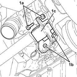
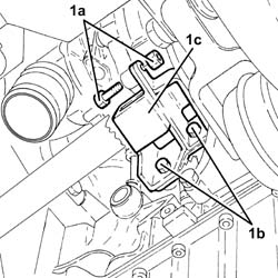
1. Undo the bolt (1a) and the three fixing bolts (1b) and remove the turbocharger mounting bracket (1c) from the cylinder block/crankcase.
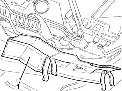
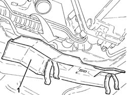
1. Remove the steering box heat shield.
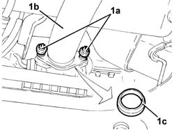
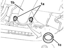
1. Undo the bolts (1a) fixing the exhaust pipe (1b) and keep the metal gasket (1c).
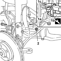
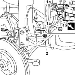
2. Undo the fixing nut (1a) and, using a special extractor (1b), remove the steering track rod end (1c) from its housing.
Then move the exhaust pipe out of the working area.
1. Undo the fixing nut (1a) and, using a special extractor (1b), remove the steering track rod end (1c) from its housing.
Undo the bolts fixing the steering knuckle to the shock absorber.
| Description | Code | Function | |
|---|---|---|---|
| 1b | Head extractor | Ball joint removal |
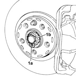
Remove the safety clip (1a) and remove the split pin (1b), then undo the nut underneath.
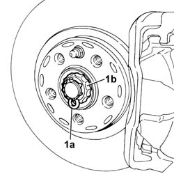
Release the right driveshaft from the housing.
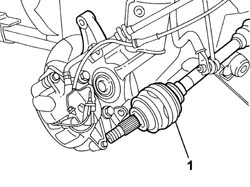
Undo the fixing nuts (1a) and remove the intermediate driveshaft and right driveshaft assembly (1b) from the wheel arch.
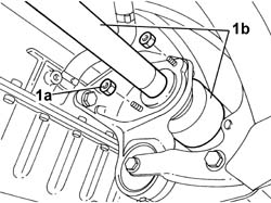
1. Undo the retaining bolts.
2. Remove the intermediate driveshaft support.
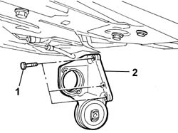
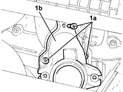
1. Undo the bolts (1a) fixing the flange joining the exhaust pipe and the turbocharger (1b).
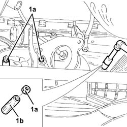
1. Undo exhaust manifold nuts (1b), recover spacers (1b) and release the manifold from the studs.
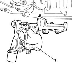
1. Release and remove the turbocharger and exhaust manifold assembly.
Refitting
Position the exhaust manifold and turbocharger assembly in their seat.
Position the spacers and tighten the nuts to torque.
Fit the flange joining the exhaust pipe and turbocharger and tighten the bolts.
Fit the intermediate half-axle mount and tighten the bolts.
| daNm | Fastening | Component | dia |
|---|---|---|---|
| 4.5 | Bolt | INTERMEDIATE DRIVE SHAFT MOUNT |
Fit the intermediate drive shaft with drive shaft and tighten the bolts securing it to the intermediate drive shaft.
| daNm | Fastening | Component | dia |
|---|---|---|---|
| 1.75 | Bolt | INTERMEDIATE DRIVE SHAFT |
Position the knuckle in its seat and tighten the bolts securing it to the shock absorber to torque.
| Value daNm | Fastening | Component | dia | |
|---|---|---|---|---|
| (Shock absorber) 9 | Bolts | FRONT HUB STRUT |
Tighten the nut securing the drive shaft to the wheel hub to torque.
| Value daNm | Fastening | Component | dia | |
|---|---|---|---|---|
10 + 60° | Nut | FRONT HUBS COMPLETE WITH BEARING |
Fit the split pin and position the safety clip.
| Value daNm | Fastening | Component | dia | |
|---|---|---|---|---|
| (steering knuckle) 4 | Nut | ADJUSTABLE STEERINGI LINK JOINTS (C-S) |
Fit the steering link on the knuckles and tighten the nut to torque.
Remove the steering box heat shield.
Position the exhaust pipe and secure to the turbine flange by tightening to torque.
| daNm | Fastening | Component | dia |
|---|---|---|---|
| 4.5 | Nut | EXHAUST PIPE |
Fit the turbocharger bracket in its seat.
| daNm | Fastening | Component | dia |
|---|---|---|---|
| 3.0 | Bolt | TURBOCHARGER BRACKET |
See
Op. 1084B42 ENGINE OIL RETURN PIPE FROM TURBO - R + R
See
Op. 1084B40 ENGINE OIL DELIVERY PIPE TO TURBOCHARGER - R + R
See
Op. 1048B10 RIGID SUPPLY PIPE (ONE) BETWEEN TURBOCHARGER AND HEAT EXCHANGER -R.R.
See
Op. 1080C80 EXHAUST GAS/WATER HEAT EXCHANGER FOR EGR SYSTEM - R.R
See
Op. 1080C54 EXHAUST GAS SUPPLY PIPE FROM E.G.R. VALVE TO INTAKE MANIFOLD - R.R.
See
Op. 1048A50 TURBOCHARGER AIR INTAKE PIPE - R.R.
See
Op. 1048A44 HOSE FROM FILTER TO TURBOCHARGER AIR INLET PIPE - REPLACE
See
Op. 1048B22 AIR DELIVERY HOSE FROM HEAT EXCHANGER TO INTAKE MANIFOLD - R + R
See
Op. 1084A10 ENGINE OIL - CHECK LEVEL AND TOP UP IF NECESSARY
See
Op. 5050B38 WINDSCREEN WIPER ASSEMBLY - R+R OR REPAIR
See
Op. 7055A18 L/H OR R/H SIDE RUBBING STRIP (ONE) FOR FRONT DOOR - R+R
See
Op. 5050B34 WINDSCREEN WIPER ARM/S COMPLETE WITH BLADE - R+R
Both
See
Op. 5010B18 CLIMATE CONTROL UNIT AIR INTAKE - R.R.
See
Op. 5530B56 BATTERY DRIP TRAY COVER - R.R.
See
Op. 7055B54 UNDER ENGINE PROTECTION/GUARD - R.R.
See
Op. 7055B91 RIGHT FRONT WHEEL ARCH LINER - R.R.
See
Op. 4450B04 RIGHT FRONT WHEEL - R.R
Check the engine fluid levels and top up if necessary.
Removing
See
Op. 4450B04 RIGHT FRONT WHEEL - R.R
See
Op. 7055B91 RIGHT FRONT WHEEL ARCH LINER - R.R.
See
Op. 7055B54 UNDER ENGINE PROTECTION/GUARD - R.R.
See
Op. 5530B56 BATTERY DRIP TRAY COVER - R.R.
See
Op. 5010B18 CLIMATE CONTROL UNIT AIR INTAKE - R.R.
See
Op. 5050B34 WINDSCREEN WIPER ARM/S COMPLETE WITH BLADE - R+R
Both
See
Op. 7055A18 L/H OR R/H SIDE RUBBING STRIP (ONE) FOR FRONT DOOR - R+R
See
Op. 5050B38 WINDSCREEN WIPER ASSEMBLY - R+R OR REPAIR
See
Op. 1048A10 AIR FILTER ASSEMBLY - R.R.
See
Op. 1048B22 AIR DELIVERY HOSE FROM HEAT EXCHANGER TO INTAKE MANIFOLD - R + R
See
Op. 1048A44 HOSE FROM FILTER TO TURBOCHARGER AIR INLET PIPE - REPLACE
See
Op. 1048A50 TURBOCHARGER AIR INTAKE PIPE - R.R.
See
Op. 1080C54 EXHAUST GAS SUPPLY PIPE FROM E.G.R. VALVE TO INTAKE MANIFOLD - R.R.
See
Op. 1080C80 EXHAUST GAS/WATER HEAT EXCHANGER FOR EGR SYSTEM - R.R
See
Op. 1048B10 RIGID SUPPLY PIPE (ONE) BETWEEN TURBOCHARGER AND HEAT EXCHANGER -R.R.
See
Op. 1084B40 ENGINE OIL DELIVERY PIPE TO TURBOCHARGER - R + R
See
Op. 1084B42 ENGINE OIL RETURN PIPE FROM TURBO - R + R
1. Undo the bolt (1a) and the three fixing bolts (1b) and remove the turbocharger mounting bracket (1c) from the cylinder block/crankcase.
1. Remove the steering box heat shield.
1. Undo the bolts (1a) fixing the exhaust pipe (1b) and keep the metal gasket (1c).
Then move the exhaust pipe out of the working area.
1. Undo the fixing nut (1a) and, using a special extractor (1b), remove the steering track rod end (1c) from its housing.
2. Undo the bolts fixing the steering knuckle to the shock absorber.
| Description | Code | Function | |
|---|---|---|---|
| 1b | Head extractor | Head extraction |
1. Remove the safety clip (1a) and remove the split pin (1b), then undo the nut underneath.
1. Release the right driveshaft from the housing.
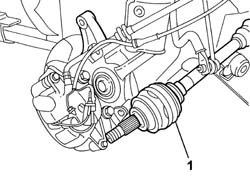
1. Undo the fixing nuts (1a) and remove the intermediate driveshaft and right driveshaft assembly (1b) from the wheel arch.
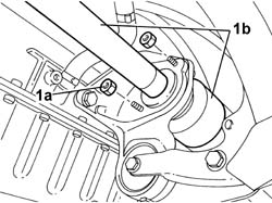
1. Undo the retaining bolts.
2. Remove the intermediate driveshaft support.
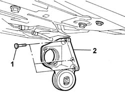
1. Undo the bolts (1a) fixing the flange joining the exhaust pipe and the turbocharger (1b).
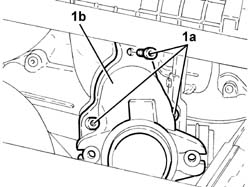
1. Undo exhaust manifold nuts (1b), recover spacers (1b) and release the manifold from the studs.
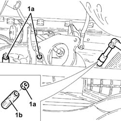
1. Release and remove the turbocharger and exhaust manifold assembly.
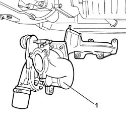
Refitting
Position the exhaust manifold and turbocharger assembly in their seat.
Position the spacers and tighten the nuts to torque. - Fit the flange joining the exhaust pipe and turbocharger and tighten the fixing bolts.
Fit the intermediate half-axle mount and tighten the bolts.
| da Nm | Fastening | Component | dia |
|---|---|---|---|
| 4.5 | Bolt | INTERMEDIATE DRIVESHAFT MOUNT |
Fit the intermediate drive shaft with drive shaft and tighten the bolts securing it to the intermediate drive shaft.
| da Nm | Fastening | Component | dia |
|---|---|---|---|
| 1.75 | Bolt | INTERMEDIATE DRIVE SHAFT |
Position the knuckle in its seat and tighten the bolts securing it to the shock absorber to torque.
| Value daNm | Fastening | Component | dia | |
|---|---|---|---|---|
| (Shock absorber) 9 | Bolts | FRONT HUB STRUT |
Tighten the nut securing the drive shaft to the wheel hub to torque.
| Value daNm | Fastening | Component | dia | |
|---|---|---|---|---|
10 + 60° | Nut | FRONT HUBS COMPLETE WITH BEARING |
Fit the split pin and position the safety clip.
| Value daNm | Fastening | Component | dia | |
|---|---|---|---|---|
| (steering knuckle) 4 | Nut | ADJUSTABLE STEERINGI LINK JOINTS (C-S) |
Fit the steering link on the knuckles and tighten the nut to torque.
Remove the steering box heat shield.
Position the exhaust pipe and secure to the turbine flange by tightening to torque.
| da Nm | Fastening | Component | dia |
|---|---|---|---|
| 4.5 | Nut | EXHAUST PIPE |
Fit the turbocharger bracket in its seat.
| da Nm | Fastening | Component | dia |
|---|---|---|---|
| 3.0 | Bolt | TURBOCHARGER MOUNTING BRACKET |
See
Op. 1084B42 ENGINE OIL RETURN PIPE FROM TURBO - R + R
See
Op. 1084B40 ENGINE OIL DELIVERY PIPE TO TURBOCHARGER - R + R
See
Op. 1048B10 RIGID SUPPLY PIPE (ONE) BETWEEN TURBOCHARGER AND HEAT EXCHANGER -R.R.
See
Op. 1080C80 EXHAUST GAS/WATER HEAT EXCHANGER FOR EGR SYSTEM - R.R
See
Op. 1080C54 EXHAUST GAS SUPPLY PIPE FROM E.G.R. VALVE TO INTAKE MANIFOLD - R.R.
See
Op. 1048A50 TURBOCHARGER AIR INTAKE PIPE - R.R.
See
Op. 1048A44 HOSE FROM FILTER TO TURBOCHARGER AIR INLET PIPE - REPLACE
See
Op. 1048B22 AIR DELIVERY HOSE FROM HEAT EXCHANGER TO INTAKE MANIFOLD - R + R
See
Op. 5050B38 WINDSCREEN WIPER ASSEMBLY - R+R OR REPAIR
See
Op. 7055A18 L/H OR R/H SIDE RUBBING STRIP (ONE) FOR FRONT DOOR - R+R
See
Op. 5050B34 WINDSCREEN WIPER ARM/S COMPLETE WITH BLADE - R+R
Both
See
Op. 5010B18 CLIMATE CONTROL UNIT AIR INTAKE - R.R.
See
Op. 5530B56 BATTERY DRIP TRAY COVER - R.R.
See
Op. 7055B54 UNDER ENGINE PROTECTION/GUARD - R.R.
See
Op. 7055B91 RIGHT FRONT WHEEL ARCH LINER - R.R.
See
Op. 4450B04 RIGHT FRONT WHEEL - R.R
Check the engine fluid levels and top up if necessary.
Parts & tools for this job Staging For 2002 Fiat Ulysse
- PARTExhaust gasketSearch: Fiat Ulysse 2002 exhaust gasket
- TOOLPenetrating oilSearch: penetrating oil
- TOOLOBD2 scannerSearch: OBD2 scanner
Links open Amazon search results in a new tab. As an Amazon Associate I earn from qualifying purchases.