
Subassembly graphic index
- Make
- Fiat
- Model
- Ulysse Factory Service Manual
- Year
- 2002–2010
- Section
- Engine air supply circuit › Subassembly graphic index
SUBASSEMBLY GRAPHIC INDEX
INTRODUCTION
The intake air is filtered and directed towards the exhaust gas turbocharger via the flow meter which measures the flow rate and the temperature of the turbocharger outlet air before reaching the engine and the compressed air is cooled by passing through the air/air heat exchanger (intercooler).
The engine air supply circuit also includes:
- the EGR (exhaust gas recirculation) circuit which makes it possible to introduce a certain quantity of exhaust gases, lacking in oxygen, into the intake manifold.
The metering is controlled by the NCM according to the engine temperature, load and speed.
Op. 1080C EXHAUST GAS RECIRCULATION SYSTEM (E.G.R.)
- the intake air heating circuit; this device is designed to increase the temperature of the exhaust gases increasing the temperature of the intake air in order to facilitate the regeneration of the FAP (particle filter).
This device is only activated during the FAP regeneration stage.
Op. 1080B EXHAUST EMISSION CONTROL SYSTEM
Diagram showing engine air supply circuit
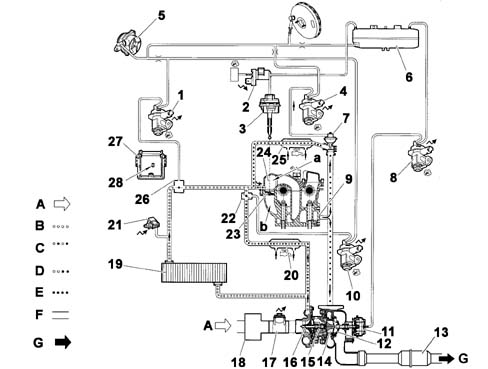
A, Intake air
B, Pressurized air
C, Exhaust gas plus air
D, Intake air heating circuit
E, Exhaust gas recirculation circuit EGR
F, Vacuum air circuit
G, Burnt gases exhaust
| 1, EGR valve casing solenoid valve - 1263 | 15, Variable geometry turbocharger |
| 2, Swirl solenoid valve - 1264 | 16, Compressor turbine impeller |
| 3, Swirl control actuator | 17, Flow meter plus air temperature sensor - 1310 |
| 4, EGR exhaust gas recirculation regulation valve - 1253 | 18, Intake air filter |
| 5, Vacuum pump | 19, Air/air heat exchanger (intercooler) |
| 6, Vacuum reservoir | 20, Water/water heat exchanger (pre-heating of intake air - FAP) |
| 7, Exhaust gas recirculation valve (EGR) | 21, Intake air pressure sensor - 1312 |
| 8, Turbo pressure regulation solenoid - 1233 | 22, Intake air heater throttle valve |
| 9, Exhaust gas manifold | 23, Swirl throttle valve |
| 10, Intake air heater solenoid valve - 1285 | 24, Intake air distributor |
| 11, Supercharging regulation piston pneumatic control actuator | 25, Exhaust gas/water heat exchanger |
| 12, Supercharging regulation piston | 26, EGR valve casing |
| 13, FAP particle filter plus catalyzer | 27, Engine Management node NCM - 1320 |
| 14, Turbine impeller | 28, Atmospheric pressure sensor (integrated in the NCM) - 1320 |
VARIABLE SWIRL
Diagram showing device
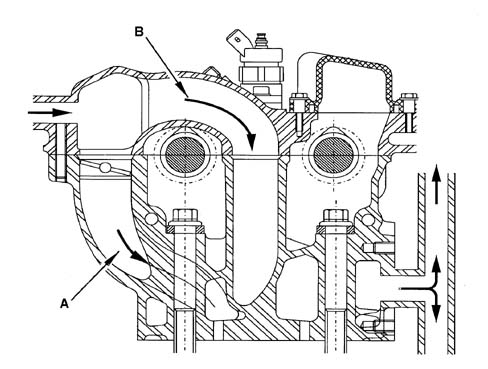
| A, Helical inlet duct (H) | B, Tangential inlet duct |
DESCRIPTION
The variable swirl device is designed to guarantee optimum turbulence of the air in the combustion chamber during the intake stage, according to the engine operation, in order to produce the best compromise between performance and pollutant emissions.
OPERATION
As a result of its shape, the helical duct (H) creates a high degree of turbulence for the intake air flow and this movement, known as swirl, also persists in the combustion chamber.
The shape of the tangential duct (T), normally closed by a throttle shutter, provides the intake air flow with a mainly axial rather than rotary element.
Throttle valves
There are throttle valves on each intake duct and they are activated by a pilot actuator and in certain circumstances by a solenoid valve.
The opening of the throttle valves is permitted in the following conditions:
- engine speed above: 2100 rpm at 80°C; 2500 rpm at 0° C
- injected flow rate above 40 mg/cycle.
Advantages of variable swirl:
- decrease in the formation of carbon particles as a result of the improvement in combustion at low engine speeds;
- good compromise between performance and emissions because the helical ducts (H) plus the tangential ducts (T) allow optimum cylinder filling.
Diagram showing operation of variable swirl device
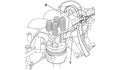
H, Helical inlet ducts
T, Tangential inlet ducts
SWIRL SOLENOID VALVE
The swirl solenoid valve (1264) operates the actuator and is located by the thermostat casing, on the engine flywheel side.
Description
The solenoid valve places the vacuum pump and the swirl pneumatic actuator in contact.
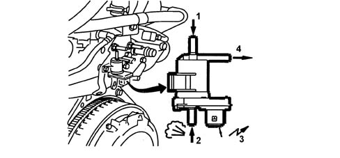
| 1, Vacuum reservoir vacuum intake | 3, Electrical connection |
| 2, Atmospheric pressure inlet | 4, Outlet to actuator |
Operation
The operation of the solenoid valve is the RCO type (Cyclical Opening Ratio) and is managed by a specific map (NCM) dependent on the intake air pressure sensor signal.
The solenoid valve is subject to the following variables:
- atmospheric pressure;
- vacuum supplied by the vacuum pump;
The pressure supplied by the solenoid lies between atmospheric pressure and vacuum pump vacuum level.
The swirl actuator is closed when it is not pneumatically operated.
Intake air pressure sensor
The regulation of the supercharging pressure is gradual and it is managed by the NCM on the basis of an engine management strategy that varies according to the engine speed and load.
This adjustment is implemented according to the supercharging pressure.
The data for this pressure value is supplied by the intake air pressure sensor, located on the air/air heat exchanger (intercooler).
View of air pressure sensor fitting
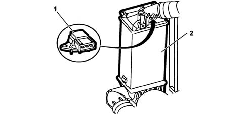
| 1, Intake air pressure sensor | 2, Air/air heat exchanger (intercooler) |
VACUUM RESERVOIR
The vacuum reservoir, which has a capacity of 0.5 litres, is fitted in the engine compartment, near the brake servo.
The vacuum circuit includes three 0.55 mm jets.
DESCRIPTION
The vacuum reservoir makes it possible to maintain sufficient braking assistance if the following components are operated simultaneously:
- swirl valve.
- intake air heater valve.
- supercharging regulation piston pneumatic control actuator.
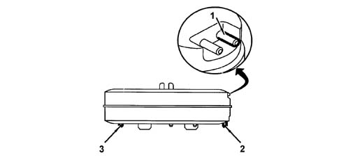
1, Connection to the vacuum pump
2, Vacuum outlet to the swirl valve
3, Vacuum outlet to the supercharging regulation piston pneumatic control actuator
CONNECTIONS FOR THE SOLENOID VALVES
The connections for the solenoid valves operating the devices should correspond to the descriptions below:
- turbo pressure regulation solenoid; white/grey pipe by the white mark on the solenoid valve.
- swirl solenoid valve. connections without provisions.
- EGR exhaust gas recirculation regulation valve. white/grey pipe by the white mark on the solenoid valve.
- EGR valve casing solenoid valve. white/grey by the white mark on the solenoid valve.
- intake air heater throttle valve solenoid valve: white/grey by the white mark on the solenoid valve.
- intake air heater valve: brown pipe by the brown capsule.
- EGR valve casing: black pipe by the black capsule.
Parts & tools for this job Staging For 2002 Fiat Ulysse
- PARTEngine gasket setSearch: Fiat Ulysse 2002 engine gasket set
- TOOLTorque wrenchSearch: 3/8 inch torque wrench
- TOOLFeeler gauge setSearch: feeler gauge set
Links open Amazon search results in a new tab. As an Amazon Associate I earn from qualifying purchases.