
Stalk unit assembly - r+r
- Make
- Fiat
- Model
- Ulysse Factory Service Manual
- Year
- 2002–2010
- Section
- Warning and manoeuvring indicators › Stalk unit assembly - r+r
STALK UNIT ASSEMBLY - R+R
Removing
Op. 5530B56 BATTERY DRIP TRAY COVER - R.R.
- Disconnect the negative battery terminal.
Op. 7040A26 STEERING COLUMN TRIM - R+R
Before working on the Air Bag system, follow the safety instructions for working on the system very carefully (See 5580C - Air Bag System - Precautions).
Op. 5580C18 AIR BAG MODULE - R+R
Before removing the steering wheel, position the wheels as parallel as possible to the longitudinal axis of the vehicle.
Op. 4110A10 STEERING WHEEL - R+R FOR REPLACEMENT OR CHECKS
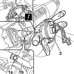
1. Loosen the collar (1b) bolt (1a).
- Act on the plastic tabs and release the steering column switch unit from the steering column.
2. Disconnect the electrical connections (2a) and (2b).
3. Remove the steering column switch unit complete with clock spring.
The clock spring is fitted with a device that automatically stops it from rotating when it is removed. Avoid forcing it to rotate.
If the steering column switch unit is being reused, it is advisable, for extra safety, to secure the two clock spring plates to prevent accidental rotation.
Refitting
- Check that the steering column switch unit is not damaged and, if necessary, conduct an electrical test.
- Connect the electrical connections.
- Position the steering columnn switch unit and tighten the collar bolt.
- If the steering column switch unit is being reused, release the plates from any fastenings positioned previously.
- If the steering column switch unit is being replaced with a new one, remove the clock spring safety tab.
Op. 4110A10 STEERING WHEEL - R+R FOR REPLACEMENT OR CHECKS
Op. 5580C18 AIR BAG MODULE - R+R
Op. 7040A26 STEERING COLUMN TRIM - R+R
- Connect the negative battery terminal.
Op. 5530B56 BATTERY DRIP TRAY COVER - R.R.
- Check the operation of the systems involved using the Examiner or other diagnostic equipment.
Parts & tools for this job Staging For 2002 Fiat Ulysse
- TOOLDigital multimeterSearch: automotive digital multimeter
- PARTAssorted fuse kitSearch: car fuse assortment kit
- TOOLWire crimper and connector kitSearch: wire crimper connector kit
Links open Amazon search results in a new tab. As an Amazon Associate I earn from qualifying purchases.