
Connect control unit support - r.r.
- Make
- Fiat
- Model
- Ulysse Factory Service Manual
- Year
- 2002–2010
- Section
- Special accessories › Connect control unit support - r.r.
CONNECT CONTROL UNIT SUPPORT - R.R.
Removing
Op. 5530B56 BATTERY DRIP TRAY COVER - R.R.
- Disconnect the negative battery terminal.
Op. 7040A74 TRIM UNDER CONTROL PANEL - R.R.
Op. 5010B66 AIR DUCT BETWEEN TIMING CASING AND CENTRE VENT IN DASHBOARD - R.R.
Op. 5010C30 CENTRAL AIR OUTLET ON FASCIA - R+R
Op. 5580P20 CENTRALINA DEL CONNECT - S.R.
1. Undo the retaining bolts.
2. Remove the Connect control unit support.
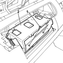
Refitting
- Position the Connect control unit support and tighten the fixing bolts
Op. 5580P20 CENTRALINA DEL CONNECT - S.R.
Op. 5510C30 ENGINE TIMING SENSOR - R+R
Op. 5010B66 AIR DUCT BETWEEN TIMING CASING AND CENTRE VENT IN DASHBOARD - R.R.
Op. 7040A74 TRIM UNDER CONTROL PANEL - R.R.
- Connect the negative battery terminal.
Op. 5530B56 BATTERY DRIP TRAY COVER - R.R.
Removing
Op. 5530B56 BATTERY DRIP TRAY COVER - R.R.
- Disconnect the negative battery terminal.
[All]
Op. 7065C30 INTERIOR L/H OR R/H GRAB HANDLE (ONE) - R+R
Op. 7040H30 FRONT PILLAR TRIM - R R
Op. 7040H42 REAR PILLAR TRIM - R R
Op. 7065C68 REAR VIEW MIRROR - R+R
Op. 7065C62 ADDITIONAL INTERIOR REAR VIEW MIRROR - R.R.
Op. 7040E10 FRONT COURTESY LIGHT - R+R
Op. 7040E12 CENTRAL COURTESY LIGHT - R+R
Op. 7040E16 REAR COURTESY LIGHT - R+R
Op. 7040H33 GLASSES HOLDER (1) LH OR RH, ON ROOF TRIM - R R
[Both]
Op. 7065C34 L/H OR R/H SUN BLIND (ONE) - R+R
Op. 7040H16 ROOF PANEL LINING - R R
Op. 7040A74 TRIM UNDER CONTROL PANEL - R.R.
Op. 5010B66 AIR DUCT BETWEEN TIMING CASING AND CENTRE VENT IN DASHBOARD - R.R.
Op. 5010C30 CENTRAL AIR OUTLET ON FASCIA - R+R
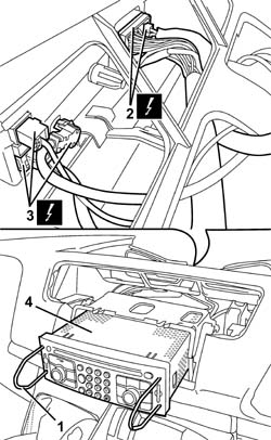
1. Using tools with the parts code no. 46515517, partly extract the Connect control unit.
2. Disconnect the electrical connections.
3. Disconnect the electrical connections for the aerials.
4. Remove the Connect control unit.
it is advisable to fit the probe cables at the end of the wiring harness to aid subsequent refitting.
- Apply a probe cable to the end of the wiring harness and secure with care. Withdraw the wiring harness from the centre of the instrument facia and disconnect the probe cable without removing.
- Apply a second probe cable to the end of the wiring harness and secure with care. Withdraw the wiring harness from the facia on the left side pillar side and disconnect the probe cable without removing.
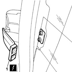
1. Disconnect the radio aerial electrical connection from the left side opening window.
1. Working at the top of the tailgate compartment, disconnect the multifunction aerial electrical connections.
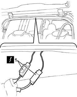
1. Release the wiring harness from the multifunction aerial to the Connect panel from the anchorages and remove from the ceiling.
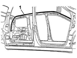
Refitting
- Positon the wiring harness from the multifunction aerial to the Connect panel on the roof and secure to its anchorage points;
- Connect the electrical connections to the multifunction aerial.
- Connect the radio aerial electrical connection from the left side opening window.
- Apply the probe lead to the end of the wiring harness and secure with care. Pass inside the facia on the left side pillar and disconnect the probe cable.
- Apply the probe lead to the end of the wiring harness and secure with care. Pass inside the central aerial of the instrument facia and disconnect the probe cable.
- Remove the Connect control unit.
- Disconnect the electrical connections for the aerials;
- Fully insert the Connect control unit until it is properly secured.
Op. 5010C30 CENTRAL AIR OUTLET ON FASCIA - R+R
Op. 5010B66 AIR DUCT BETWEEN TIMING CASING AND CENTRE VENT IN DASHBOARD - R.R.
Op. 7040A74 TRIM UNDER CONTROL PANEL - R.R.
Op. 7040H16 ROOF PANEL LINING - R R
[Both]
Op. 7065C34 L/H OR R/H SUN BLIND (ONE) - R+R
Op. 7040H33 GLASSES HOLDER (1) LH OR RH, ON ROOF TRIM - R R
Op. 7040E16 REAR COURTESY LIGHT - R+R
Op. 7040E12 CENTRAL COURTESY LIGHT - R+R
Op. 7040E10 FRONT COURTESY LIGHT - R+R
Op. 7065C62 ADDITIONAL INTERIOR REAR VIEW MIRROR - R.R.
Op. 7065C68 REAR VIEW MIRROR - R+R
Op. 7040H42 REAR PILLAR TRIM - R R
Op. 7040H38 CENTRAL PILLAR UPPER ELEMENT - R R
Op. 7040H30 FRONT PILLAR TRIM - R R
[All]
Op. 7065C30 INTERIOR L/H OR R/H GRAB HANDLE (ONE) - R+R
- Connect the negative battery terminal.
Parts & tools for this job Staging For 2002 Fiat Ulysse
- TOOLDigital multimeterSearch: automotive digital multimeter
- PARTAssorted fuse kitSearch: car fuse assortment kit
- TOOLWire crimper and connector kitSearch: wire crimper connector kit
Links open Amazon search results in a new tab. As an Amazon Associate I earn from qualifying purchases.