
Engine compartment node (ndvim)
- Make
- Fiat
- Model
- Ulysse Factory Service Manual
- Year
- 2002–2010
- Section
- Instrument/gauge electrical circuits › Engine compartment node (ndvim)
ENGINE COMPARTMENT NODE (NDVIM)
INTRODUCTION
The engine compartment node is located on the right side of the actual engine compartment (near the windscreen washer fluid reservoir).
NDVM FUNCTION
The NDVM has the task of distributing the power supplies via:
- Relays.
- Fuses.
- Mini fuses.
- Maxi fuses.
housed in it.
The NDVM comprises 2 modules (1 and 2) and guarantees the following functions:
- Distribution and protection of the main power supply lines and different functions
- Protection of the engine function power supply lines
- Communcation via the VAN CAR 1 network
- Interconnection
- Switching and protection of different functions: Main relay (powerlatch) and engine management power, fuel pump interruption, climate control vent, horn, main/dipped beam headlamps, fog lights, front/rear screen washers, headlamp washer, front windscreen wiper
- Rereading outputs
- Sensor signal recording.
The battery lead is fastened at module 1 of the NDVM (power module) which has the task of distributing the +BATT power supplies to the various components in the engine compartment (NDVM module 2, NFR, alternator) and in the passenger compartment (anti-theft devide, NBC).
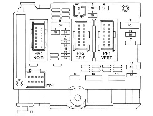
Starting from the positive battery lead, module 1 guarantees:
- distribution and protection via the maxi fuse for the +BATT electrical power supplies to the components connected via the main wiring,
- the electrical power supply (+BAT Power) for module 2,
- the electrical interconnection between the battery lead and the alternator/starter motor/spark plugs connection.
Starting from the +BATT supplied by module 1 and the anti-theft enablement, module 2 guarantees the distribution, protection and interupption of the power supply (via relays) for the components connected by means of the main and engine wiring.
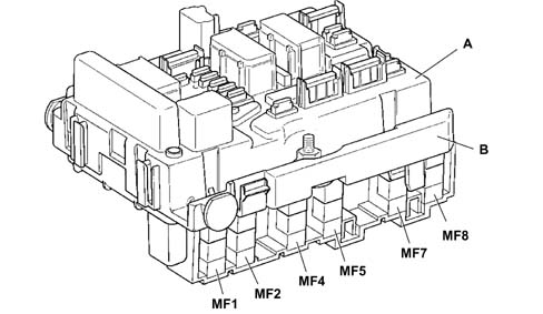
- A - module 1
- B - module 2
Distribution of the power supplies by fuse, with ignition at MAR for module 2:
The NDVM is supplied with the ignition ON.
The following components are supplied with the ignition ON, by fuse, by the NDVM:
- NCA, reversing switch/reversing light,
- (NCM, NFR),
- water in diesel sensor (for diesel engines),
- Preheating node (for diesel engines),
- air flow meter (for diesel engines),
- speed sensor (for petrol engines),
- gas discharge headlamps,
- Engine cooling fan assembly relay,
- engine coolant level (for diesel engines)
Distribution of power supplies by fuse for module 2:
- Additive Control Node (for diesel engines),
- Additive injector (for diesel engines),
Distribution of power supplies by relay and fuse for module 2:
- NCM,
- Left/right dipped headlamps,
- Left/right main beam headlamps,
- Fog lights,
- Front windscreen wiper,
- Front/rear windscreen washer pump,
- Headlamp washer pump,
- Signal,
- Additional vents,
- NCM actuators/sensors,
- NCM,
- Fuel pump,
- Air pump (for petrol engines),
- Ignition coil (for petrol engines),
- Injectors (for petrol engines),
- EGR solenoid valve (for petrol engines),
- Lambda sensor (for petrol engines),
- EGR solenoid valve,
- Turbo pressure regulator solenoid valve (waste gate) (for diesel engines)
- Diesel heater (for diesel engines),
Powerlatch and power electrical supply for engine management system:
In the case of an impact, the NBC requests the NDVM to cut off the fuel pump supply via the VAN CAR network.
The NDVM cuts off the "power activator" electrical supply for the fuel pump.
Operating procedure
There are 4 operating modes for the NDVM electronics:
- "system inactive or standy" mode: with +15 or +VAN power supplies below 5.5 V.
- powerlatch mode: +15 and +VAN power supplies below 5.5V and the main relay controlled by the engine management control unit.
- "system reactivated" mode: all the functions are active. Effective communication on the VAN multiplex network.
- emergency mode if there is no VAN communication.
PROTECTION THROUGH NDVM MODULE 1 FUSES
The table below illustrates the specifications of the maxi fuses in the NDVM:
Petrol versions
| ABS | ABS | ESP | ESP | |
|---|---|---|---|---|
| Maxi fuse | Function | Amperage | Function | Amperage |
| MF1 | Second speed fan | 50A | Second speed fan | 50A |
| MF2 | ABS | 60A | ESP | 50A |
| MF3 | ESP solenoid valve | 30A | ||
| MF4 | NBC1 | 60A | NBC1 | 60A |
| MF5 | NBC2 | 70A | NBC2 | 70A |
| MF6 | First speed fan | 30A | First speed fan | 30A |
| MF7 | Anti-theft device | 40A | Anti-theft device | 40A |
| MF8 | Climate control | 50A | Climate control | 50A |
Diesel versions
| ABS | ABS | ESP | ESP | |
|---|---|---|---|---|
| Maxi fuse | Function | Amperage | Function | Amperage |
| MF1 | Second speed fan | 50A | Second speed fan | 50A |
| MF2 | ABR | 60A | ABR | 60A |
| MF3 | BURNER | 30A | BURNER | 30A |
| MF4 | NBC1 | 60A | NBC1 | 60A |
| MF5 | NBC2 | 70A | NBC2 | 70A |
| MF6 | First speed fan | 30A | First speed fan | 60A |
| MF7 | Anti-theft device | 40A | Anti-theft device | 40A |
| MF8 | Climate control | 50A | Climate control | 50A |
NDVM MODULE 2 PROTECTION
Moduel 2 of the NDVM:
- establishes the electrical supply, via the powerlatch relay (RL1), for the engine management system if the following conditions occur: +30 power supply present, operation of powerlatch relay via engine management control unit supplied, in the first place, by +15 NDVM
- establishes the electrical supply, via the power relay (RL2), for the sensors and activators (including the fuel pump) for the enigne management system if the following conditions occur: +30 power supply present, +VAN CAR or +15 supply present, operation of powerlatch relay by means of engine management control unit, operation of power relay by means of engine management control unit, impact information.
establishes the electrical supply, via the power relay (RL2), for the sensors and activators (including the fuel pump) for the enigne management system if the following conditions occur: +30 power supply present, +VAN CAR or +15 supply present, operation of powerlatch relay by means of engine management control unit, operation of power relay by means of engine management control unit, impact information.
Module 2 also guarantees protection if the battery polarity is reversed.
| FUSES | Amperage | Function |
|---|---|---|
| F1 | 10A | Reversing lights |
| Gas discharge headlamps, | ||
| Engine cooling fan relay control | ||
| Engine coolant level (diesel) | ||
| Heater plugs node (diesel), | ||
| Air flow meter (diesel) | ||
| Water presence sensor (diesel) | ||
| Vehicle speed sensor (diesel), | ||
| F2 | 15A | Fuel pump |
| EV EGR (diesel) | ||
| EV turbo pressure regulation (waste gate valve) (diesel) | ||
| F3 | 10A | ABS/ESP control unit |
| F4 | 10A | NCA control unit |
| Starting relay control | ||
| Shift lock relay control | ||
| NCA shift lock | ||
| Engine management control unit | ||
| F5 | 10A | Additive injector (diesel) |
| NAD (diesel) | ||
| F6 | 15A | Fog light |
| F7 | 20A | Headlamp washer pump |
| F8 | 20A | Main relay NCM |
| Turbo pressure regulation solenoid valve (waste gate valve) (diesel) | ||
| F9 | 15A | Left dipped headlamp |
| Front headlamp alignment adjustment sensor | ||
| Rear lamps alignment adjustment sensor | ||
| F10 | 15 | Right dipped headlamp |
| F11 | 10 | Left main beam headlamp |
| F12 | 10 | Right main beam headlamp |
| F13 | 15A | Horn |
| F14 | 10A | Front windscreen washer pump |
| F15 | 30A | EGR throttle valve solenoid (diesel0 |
| Swirl solenoid valve (diesel0 | ||
| Air heater solenoid valve (diesel 2.2 JTD) | ||
| Diesel injection pump solenoid valve (diesel) | ||
| Downstream Lambda sensor heating Rg A (petrol) | ||
| Upstream Lambda sensor heating Reg. A (petrol) | ||
| Diesel heater (diesel) | ||
| Injectors (petrol) | ||
| EGR solenoid valve (diesel 2.0 JTD) | ||
| Ignition coil (petrol) | ||
| Throttle valve node heater (petrol) | ||
| Canister filer scavenging solenoid valve (petrol) | ||
| F16 | 30A | Air pump (petrol) |
| F17 | 30A | Front windscreen wiper |
| F18 | 40A | Additional vents (climate control system) |
The NDVM does not guarantee sufficient protection for the additional vents, a lower capacity fuse will be added to the BMF 12 connection bridge at the side of the battery).
Retransmitted and protected power output table
Ouputs from contact relay + Fuse:
| FUNCTIONS | Relay no. and fuse | Flow rate | with | Current Type |
|---|---|---|---|---|
| ENGINE MANAGEMENT POWER LATCH RELAY | R1 (F1) | 20 A | +BAT_P | 16 A |
| ENGINE MANAGEMENT POWER RELAY | R2 (F2+F3) | 30A+15A | +BAT_P | 23 A +15 A |
| AIR PUMP RELAY | R13 (F14) | 30 A | +BAT_P | 135 A -23 A |
| * CLIMATE CONTROL VENT RELAY | R3 (F4) | 40 A | +BAT_P | 28 A -18 A |
| HEADLAMP WASHER PUMP RELAY | R12 (F13) | 20 A | +BAT_P | 55 A -15 A |
| FOG LIGHTS RELAY | R11 (F12) | 15 A | +BAT_P | 10 A |
| MAIN BEAM HEADLAMPS RELAY | R6 (F8+F9) | 10A X 2 | +BAT_P | 10 A |
| * DIPPED HEADLAMPS RELAY | R5 (F6+F7) | 15A X 2 | +BAT_P | 10 A |
| SIGNAL RELAY | R4 (F5) | 15 A | +BAT_P | 10 A |
Outputs from reversal relay:
| FUNCTIONS | Relay no. and fuse | Flow rate | with | Current |
|---|---|---|---|---|
| FRONT WINDSCREEN WASHER PUMP RELAY | R9 (F11) | 10 A | +BAT_P | 5 A |
| REARSCREEN WASHER PUMP RELAY | R10 (F11) | 10 A | +BAT_P | 5 A |
| FRONT WINDSCREEN WIPER CONTROL RELAY | R7 (F10) | 30A | +BAT_P | 10 A |
| FRONT WINDSCREEN WIPER RELAY PV GV | R8 (F10) | 30A | +BAT_P | 15 A |
CONNECTIONS
The following 5 connectors and a main supply terminal are present at the NDVM:
- 8 mm diameter flat terminal on a threaded stud (+BAT_P) +BATTERY supply terminal connected to the battery lead
- Connector B: PM1 (power connector to engine cable loom), 16-way, black
- Connector C PP1 (power connector to main cable loom), 16-way, green
- Connector D: PP2 (power connector to main cable loom), 16-way, grey
- Connector F: BAT (BATTERY connector connected to the battery lead), 2-way, black
- Connector E: EP1 (power connector to main cable loom), 10-way, black
The main cable loom is connected to the NDVM via connectors PP1, PP2, EP1.
The engine cable loom is connected to the NDVM via connector PM1.
The battery cable loom is connected to the NDVM via the 8 mm terminal.
Connector B (PM1)
2.8 mm tabs on ways 1, 8, 9 and 16.
1.5 mm tabs on the other ways.
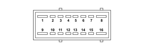
| Pin | Function |
|---|---|
| 1 | Lambda sensor |
| 2 | +15 reverse |
| 3 | Power relay control NCM |
| 4 | Oil temperature |
| 5 | Oil sensor earth |
| 6 | Oil level |
| 7 | Climate control compressor |
| 8 | Power latch relay |
| 9 | Ignition coils |
| 10 | Injectors |
| 11 | Oil pressure |
| 12 | Water in diesel sensor |
| 13 | Power latch relay control |
| 14 | Speed sensor |
| 15 | data not available |
| 16 | data not available |
Connector C (PP1)
2.8 mm tabs on ways 1, 8, 9 and 16.
1.5 mm tabs on the other ways.
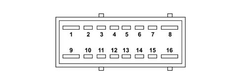
| Pin | Function |
|---|---|
| 1 | Front windscreen wiper |
| 2 | FAP |
| 3 | +30 Front windscreen wiper |
| 4 | front windscreen wiper relay control |
| 5 | reserve |
| 6 | data not available |
| 7 | Horn 2 |
| 8 | Climate control |
| 9 | Front windscreen wiper |
| 10 | Fog light |
| 11 | Rearscreen washer |
| 12 | +15 NCM |
| 13 | Earth |
| 14 | Front windscreen washer |
| 15 | Horn 1 |
| 16 | Climate control |
Connector D (PP2)
2.8 mm tabs on ways 1, 8, 9 and 16.
1.5 mm tabs on the other ways
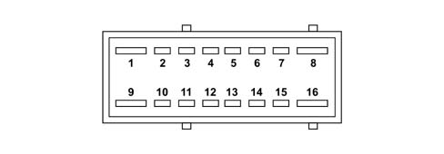
| Pin | Function |
|---|---|
| 1 | data not available |
| 2 | data not available |
| 3 | +15 NFR |
| 4 | +15 NCA |
| 5 | Earth |
| 6 | Right main beam headlamp |
| 7 | Left main beam headlamp |
| 8 | Right dipped headlamp |
| 9 | +15 |
| 10 | data not available |
| 11 | Fuel pump |
| 12 | Canister solenoid valve |
| 13 | Climate control compressor |
| 14 | Power latch relay |
| 15 | Left dipped headlamp |
| 16 | Air pump |
Distribution of connector E (EP1) stems
1.5 mm tabs on ways 1 - 10
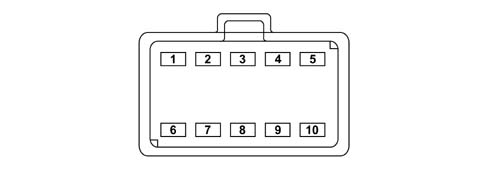
| Pin | Function |
|---|---|
| 1 | Van Car1 Data |
| 2 | Speed sensor |
| 3 | Oil sensor earth |
| 4 | Oil temperature |
| 5 | Van Car1 Data B |
| 6 | Not connected |
| 7 | Not connected |
| 8 | Earth |
| 9 | +Van Car1 |
| 10 | Oil level |
Connector F (BAT)
2.8 mm tabs on ways 1 -2
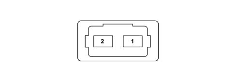
| Pin | Function |
|---|---|
| 1 | data not available |
| 2 | data not available |
DIAGNOSTICS
If VAN communication is lost and if there is a fault inside the NCM, a control device is fitted.
If there is a fault inside the main control circuit for module 2 of the NDVM, a control device guarantees that the dipped headlamps are either switched on or stay on whilst the engine is running.
The NDVM fault diagnosis takes place via the NBC by means of the VAN CAR network.
INTRODUCTION
The engine compartment node is located on the right side of the actual engine compartment (near the windscreen washer fluid reservoir).
NDVM FUNCTION
The function of the engine compartment node is to protect and distribute the power supplies to the various functions via:
- relays;
- fuses;
- minifuses;
- maxi fuses.
The NDVM consists of two combined modules (A and B):
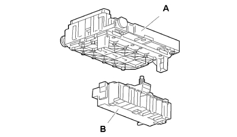
Module A (BOO1) consists of an electronic card that houses relays fuses and a microcontroller that communicates via the CAN network with body computer (M001).
Module B contains the maxifuses (fuses with a high amp rating).
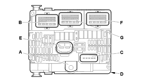
The main functions of the NDVM are:
- to distribute and protect (by means of fuses) the electrical power supplies of devices connected via the main wiring and engine wiring;
- to supply an electrical power supply to the maxifuse casing.
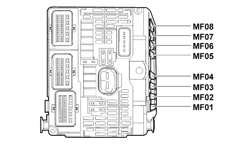
PROTECTION BY MEANS OF MAXIFUSES (CONNECTOR D)
The following table shows the devices protected by the maxifuses on the NDVM.
| Pin | Maxi fuse | Devices protected | Amp rating [A] |
|---|---|---|---|
| 1 | MF01 | MAIN FAN | 50 |
| 2 | MF02 | ESP/ABS (POWER) | 40 |
| 3 | MF03 | ESP/ABS | 30 |
| 4 | MF04 | M001 | 60 |
| 5 | MF05 | M001 | 70 |
| 6 | MF06 | FREE | |
| 7 | MF07 | FREE | |
| 8 | MF08 | FREE |
POWER SUPPLIED BY NDVM
The engine compartment junction unit (with key ON and enablement from CODE), distributes the following power supplies and protects them with fuses:
- ABS, ESP;
- water in diesel sensor;
- glow plug control unit;
- air flow sensor;
- engine cooling fan assembly relay;
- engine coolant level;
- automatic transmission control unit;
- reversing switch/reversing light;
- gas discharge headlamps;
- diesel additive control unit;
- diesel additive pump;
- low beam headlamps;
- high beam headlamps;
- fog lamps;
- front windscreen wiper;
- headlamp washer pump;
- buzzer;
- additional outlets (climate control system);
- engine control niode actuators/sensors;
- engine management control unit;
- EGR solenoid;
- turbo pressure regulator solenoid;
- diesel heater;
- front/rear screen washer pump;
- fuel pump.
In the case of an impact, the body computer instructs the NDVM to cut off the fuel pump supply via the CAN network.
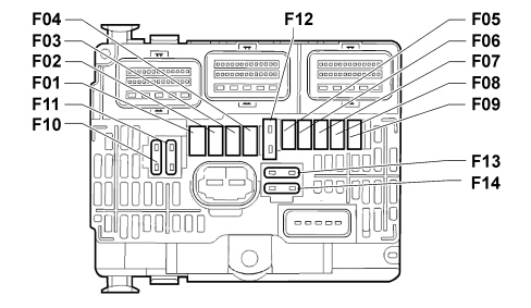
PROTECTION PROVIDED BY NDVM FUSES
| Fuse | Power supply | Supply | Amp rating [A] |
|---|---|---|---|
| F01 | +BAT | - ENGINE CONTROL UNIT - ENGINE FAN POWER RELAY - EGR SOLENOID VALVE - DIESEL PRESSURE ADJUSTMENT SOLENOID | 20 |
| F02 | +BAT | HORN | 15 |
| F03 | +BAT | WINDOW WASHER PUMP | 10 |
| F04 | +BAT | HEADLAMP WASHER PUMP | 20 |
| F05 | +15 | FUEL PUMP | 15 |
| F06 | +15 | AUTOMATIC TRANSMISSION CONTROL UNIT - AIR FLOW METER - ENGINE WATER LEVEL - SECONDARY BRAKE SWITCH - CAR RIDE CORRECTOR - PUSHBUTTON CONTACT - AUTOMATIC TRANSMISSION GEAR CONTROL UNIT | 10 |
| F07 | +15 | ESP CONTROL UNIT | 10 |
| F08 | +BAT | ENGINE IGNITION COIL | 20 |
| F10 | +BAT | - TURBINE SOLENOID - INJECTION PUMP AIR HEATER SOLENOID - EGR SOLENOID VALVE - TURBO PRESSURE ADJUSTMENT SOLENOID - RADIATOR WATER INLET SOLENOID - WATER RADIATOR SOLENOID - DIESEL HEATER | 30 |
| F11 | +BAT | ADDITIONAL OUTLETS (CLIMATE CONTROL) | 40 |
| F12 | +BAT | WINDSCREEN WIPERS | 30 |
| F13 | +15 | BODY COMPUTER | 40 |
| F14 | +BAT | FREE |
PERFORMANCE
The engine compartment junction unit node performs the following services:
- distributes and protects the +BATT and +15 power supplies of devices connected to the main wiring and engine wiring, short-circuits to earth in the event of malfunction (e.g. extended locking of an electric motor) and triggers the corresponding fuse;
- provides electrical power to the central door open/locking system;
- supplies the engine control unit and some of its devices after activation of the +15 supply;
- ensure power to the fuel pump is cut off in the event of a crash;
- supplies the Air Bag control unit with power;
- protects the circuit if the battery terminals are reversed;
- supplies the starter motor with power;
- supplies the engine cooling fan with power upon the request of the body computer via the CAN CAR network;
- controls the sound alarm upon the request of the body computer via the CAN CAR network.
- controls the low beam headlamps upon the request of the body computer via the CAN CAR network.
- controls the high beam headlamps upon the request of the body computer via the CAN CAR network.
- controls the foglamps upon the request of the body computer via the CAN CAR network.
- controls the flashers upon the request of the body computer via the CAN CAR network.
- controls the washer pump/screen wipers upon the request of the body computer via the CAN CAR network.
- controls the rear screen washer pump upon the request of the body computer via the CAN CAR network.
- controls the headlamp washer pump upon the request of the body computer via the CAN CAR network.
- controls the air condition compressor upon the request of the body computer via the CAN CAR network.
- generates a +15 signal upon the request of the body computer via the CAN CAR network and protects the supply line;
- controls +15 signal generation if communication is lost in the CAN CAR network;
- downloads the engine oil level signal and communicates signal status to the body computer via the CAN network;
- supplies a signal to excite the alternator;
- downloads the engine oil pressure signal and communicates signal status to the body computer via the CAN CAR network;
- downloads the engine oil temperature signal and communicates signal status to the body computer via the CAN CAR network;
- downloads the screen washer level signal and communicates signal status to the body computer via the CAN CAR network;
- downloads the water level signal;
- downloads the reversing light signal.
CONNECTOR PIN OUT
Connector a
This is the connector from which the NDVM receives power from the battery.
Connector b
| Pin | Description |
|---|---|
| 1 | NC |
| 2 | IGNITION COIL POWER SUPPLY |
| 3 | LAMBDA SENSRO HEATER POWER SUPPLY |
| 4 | INJECTOR POWER SUPPLY |
| 5 | ENGINE CONTROL UNIT POWER SUPPLY |
| 6 | ENGINE OIL LEVEL ANALOGUE EARTH |
| 7 | ENGINE OIL LEVEL SIGNAL |
| 8 | ENGINE MANAGEMENT POWER RELAY CONTROL |
| 9 | MAIN ENGINE MANAGEMENT RELAY CONTROL |
| 10 | NC |
| 11 | NC |
| 12 | NC |
| 13 | NC |
| 14 | NC |
| 15 | NC |
| 16 | NC |
| 17 | NC |
| 18 | NC |
| 19 | NC |
| 20 | ENGINE OIL PRESSURE INFORMATION (LOW) |
| 21 | INFORMATION ON WATER DETECTED IN DIESEL |
| 22 | ENGINE OIL TEMPERATURE SIGNAL |
| 23 | NC |
| 24 | - SOLENOID PUMP POWER SUPPLY:SWIRL - INTAKE AIR HEATING - DIESEL INJECTION PUMP - TURBO PRESS REGULATION - INTAKE AIR HEATING |
| 25 | NC |
| 26 | NC |
| 27 | NC |
| 28 | NC |
Connector c
| Pin | Description |
|---|---|
| 1 | AIR CONDITIONER COMPRESSOR CONTROL |
| 2 | IGNITION COIL CONTROL |
| 3 | ALTERNATOR EXCITATION CONTROL |
| 4 | NC |
| 5 | COOLING COMPRESSOR EARTH |
Connector e
| Pin | Description |
|---|---|
| 1 | +15 POWER SUPPLY |
| 2 | AIR CONDITIONER ADDITIONAL FAN CONTROL |
Connector f
| Pin | Description |
|---|---|
| 1 | NC |
| 2 | ENGINE FAN 3 SPEED RELAY |
| 3 | ESP CONTROL UNIT |
| 4 | AUTOMATIC TRANSMISSION CONTROL UNIT |
| 5 | FUEL PUMP CONTROL |
| 6 | NC |
| 7 | NC |
| 8 | NC |
| 9 | IGNITION CONTROL |
| 10 | NC |
| 11 | CAN CAR HIGH |
| 12 | CAN CAR LOW |
| 13 | REVERSING LIGHT CONTROL |
| 14 | NC |
| 15 | PARKING STATUS/AUTOMATIC TRANSMISSION NEUTRAL INFORMATION |
| 16 | START-UP ENABLEMENT |
| 17 | LEFT TURN SIGNAL REPEATER OUTPUT |
| 18 | RIGHT TURN SIGNAL REPEATER OUTPUT |
| 19 | EARTH |
| 20 | - POEWR STEERING POWER SUPPLY - DEBIMETER - ENGINE WATER PRE-POST HEATING CONTROL UNIT - PARKING BRAKE SENSOR |
| 21 | NC |
| 22 | CANISTER BLEED SOLENOID |
| 23 | CAN (+) POWER SUPPLY |
| 24 | NC |
| 25 | WINDSCREEN WIPER MOTOR STOP CONTROL |
| 26 | BODY EARTH |
| 27 | FAST WIPER SPEED CONTROL |
| 28 | SLOW WIPER SPEED CONTROL |
Connector g
| Pin | Description |
|---|---|
| 1 | HEADLAMP WASHER PUMP CONTROL |
| 2 | WINDOW WASHER PUMP/WIPER CONTROL |
| 3 | HORN |
| 4 | NC |
| 5 | REARSCREEN WASHER PUMP CONTROL |
| 6 | RIGHT FRONT TURN SIGNAL |
| 7 | NC |
| 8 | LEFT FRONT TURN SIGNAL |
| 9 | NC |
| 10 | NC |
| 11 | RIGHT FRONT SIDE LIGHT CONTROL |
| 12 | LEFT FRONT SIDE LIGHT CONTROL |
| 13 | RIGHT FOG LAMP POWER SUPPLY |
| 14 | ENGINE WATER LEVEL INFORMATION |
| 15 | NC |
| 16 | NC |
| 17 | NC |
| 18 | NC |
| 19 | ENGINE CONTROL UNIT POWER SUPPLY |
| 20 | NC |
| 21 | NC |
| 22 | NC |
| 23 | NC |
| 24 | LEFT FOG LAMP POWER SUPPLY |
| 25 | LEFT LOW BEAM HEADLAMP CONTROL |
| 26 | RIGHT LOW BEAM HEADLAMP CONTROL |
| 27 | RIGHT HIGH BEAM CONTROL |
| 28 | - LEFT HIGH BEAM CONTROL - HIGH BEAM HEADLAMP RELAY CONTROL (XENON LIGHTS) |
Parts & tools for this job Staging For 2002 Fiat Ulysse
- PARTEngine gasket setSearch: Fiat Ulysse 2002 engine gasket set
- TOOLTorque wrenchSearch: 3/8 inch torque wrench
- TOOLFeeler gauge setSearch: feeler gauge set
Links open Amazon search results in a new tab. As an Amazon Associate I earn from qualifying purchases.