
Power unit with manual gearbox - r + r
- Make
- Fiat
- Model
- Panda Factory Service Manual
- Year
- 2003–2012
- Section
- Engine and power unit › Power unit with manual gearbox - r + r
Power unit with manual gearbox - r + r
Removing
Place the car on a lift.
1. Move the positive battery terminal protective cover aside.
2. Undo the nut (2a) fixing the starter motor supply lead (2b) and the fuse box supply lead (2c) and disconnect them from the battery.
| Name | Connector | |
|---|---|---|
| 2c | Battery | A1E |
3. Undo the fixing nuts (3a) and disconnect the negative battery lead (3b) and the positive lead (3c).
| Name | Connector | |
|---|---|---|
| 3b | Battery | A1B |
| Name | Connector | |
|---|---|---|
| 3c | Battery | A1A |
4. Undo the nut (4a) fixing the battery (4b) and remove it.
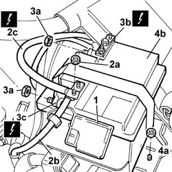
Removing
Place the car on a lift.
1. Move the positive battery terminal protective cover aside.
2. Undo the nut (2a) fixing the starter motor supply lead (2b) and the fuse box supply lead (2c) and disconnect them from the battery.
| Name | Connector | |
|---|---|---|
| 2c | Battery | A1E |
3. Undo the fixing nuts (3a) and disconnect the negative battery lead (3b) and the positive lead (3c).
| Name | Connector | |
|---|---|---|
| 3b | Battery | A1B |
| Name | Connector | |
|---|---|---|
| 3c | Battery | A1A |
4. Undo the nut (4a) fixing the battery (4b) and remove it.
1. Remove the battery cage cover.
2. Disconnect the electrical connections for the engine management control unit.
| Name | Connector | |
|---|---|---|
| 2 | Engine management control unit | M10A |
| Name | Connector | |
|---|---|---|
| 2 | Engine management control unit | M10B |
3. Undo the fixing bolt (3a) and disconnect the earth lead (3b).
| Name | Connector | |
|---|---|---|
| 3b | Engine management control unit | M10C |
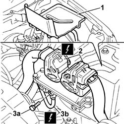
1. Remove the battery drip tray cover.
2. Disconnect the electrical connections for the engine management control unit.
| Name | Connector | |
|---|---|---|
| 2 | Engine management control unit | M10A |
| Name | Connector | |
|---|---|---|
| 2 | Engine management control unit | M10B |
3. Undo the fixing bolt (3a) and disconnect the earth lead (3b).
| Name | Connector | |
|---|---|---|
| 3b | Engine management control unit | M10C |
1. Undo the bolts fixing the battery cage.
2. Move the battery cage aside.
3. Open the fastening clips (3a) and release the wiring (3b) from the battery cage.
Remove the battery cage complete with engine management control unit.
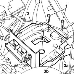
1. Undo the bolts fixing the battery cage.
2. Move the battery cage aside.
3. Open the fastening clips (3a) and release the wiring (3b) from the battery cage.
Remove the battery cage complete with engine management control unit.
1. Release the air hose from the cold air intake.
2. Undo the fixing bolts (2a) and release the fastening clip (2b).
3. Remove the air filter casing complete with hose.
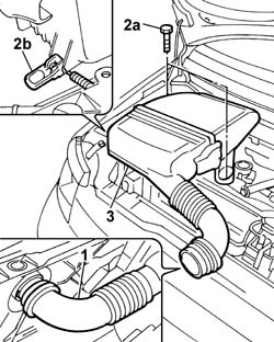
1. Release the air hose from the cold air intake.
2. Undo the fixing bolts (2a) and release the fastening clip (2b).
3. Remove the air filter casing complete with hose.
1. Undo the fixing bolts (1a) and remove the wheel (1b).
Work in the same way for both wheels.
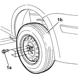
1. Undo the fixing bolts (1a) and remove the wheel (1b).
Work in the same way for both wheels.
Position a suitable container to collect the coolant.
1. Undo retaining clips (1a), disconnect lower radiator end sleeve (1b) and drain the system.
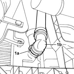
Position a suitable container to collect the coolant.
1. Undo retaining clips (1a), disconnect lower radiator end sleeve (1b) and drain the system.
1. Remove the protective cover for the engine compartment junction unit (1a) and disconnect the electrical connection (1b) underneath.
| Name | Connector | |
|---|---|---|
| 1b | Front / engine coupling | D4 |
2. Disconnect the electrical connections for the Lambda sensors.
| Name | Connector | |
|---|---|---|
| 2 | Lambda sensor on catalyzer | K17 |
| Name | Connector | |
|---|---|---|
| 2 | Lambda sensor on catalyzer -2 | K18 |
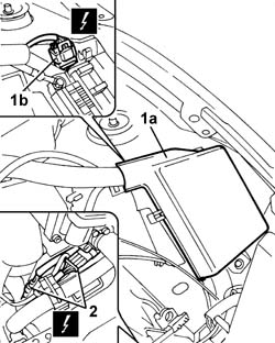
1. Remove the protective cover for the engine compartment junction unit (1a) and disconnect the electrical connection (1b) underneath.
| Name | Connector | |
|---|---|---|
| 1b | Front / engine coupling | D4 |
2. Disconnect the electrical connections for the Lambda sensors.
| Name | Connector | |
|---|---|---|
| 2 | Lambda sensor on catalyzer | K17 |
| Name | Connector | |
|---|---|---|
| 2 | Lambda sensor on catalyzer -2 | K18 |
1. Disconnect the one-way valve (1a) from the brake servo and move the pipe (1b) aside.
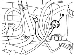
1. Disconnect the one-way valve (1a) from the brake servo and move the pipe (1b) aside.
1. Open the fastening bands (1a) and the clip (1b) and disconnect the heater pipes (1c).
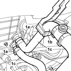
1. Open the fastening bands (1a) and the clip (1b) and disconnect the heater pipes (1c).
1. Remove the protective cap (1a) for the breather valve for the single fuel pipe (1b) and discharge the fuel pressure using the tool (1c).
Collect the fuel in a suitable container.
| Name | Country | |
|---|---|---|
| 1c | Rapid connector | 1.870.684.000 |
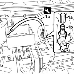
1. Remove the protective cap (1a) for the breather valve for the single fuel pipe (1b) and discharge the fuel pressure using the tool (1c).
Collect the fuel in a suitable container.
| Name | Country | |
|---|---|---|
| 1c | Rapid connector | 1.870.684.000 |
1. Disconnect the fuel supply and collection pipes.
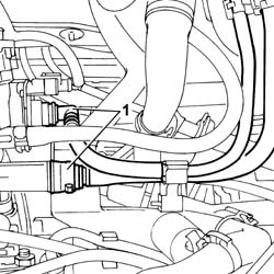
1. Disconnect the fuel supply and collection pipes.
1. Work on the throttle body (1a) and disconnect the accelerator cable (1b).
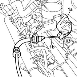
1. Work on the throttle body (1a) and disconnect the accelerator cable (1b).
1. Disconnect the electrical connection for the reversing lights switch.
| Name | Connector | |
|---|---|---|
| 1 | Reversing lights switch | I20 |
2. Undo the fixing nut (2a) and disconnect the earth cable on the gearbox (2b).
| Name | Connector | |
|---|---|---|
| 2b | Battery earth on engine | C2 |
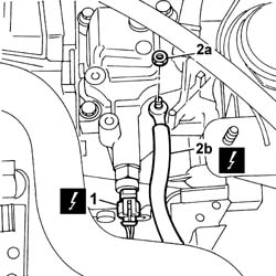
1. Disconnect the electrical connection for the reversing lights switch.
| Name | Connector | |
|---|---|---|
| 1 | Reversing lights switch | I20 |
2. Undo the fixing nut (2a) and disconnect the earth cable on the gearbox (2b).
| Name | Connector | |
|---|---|---|
| 2b | Battery earth on engine | C2 |
1. Undo the adjustment and fastening nut (1a) and disconnect the clutch cable (1b) from the thrust bearing control lever (1c).
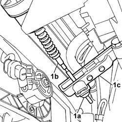
1. Undo the adjustment and fastening nut (1a) and disconnect the clutch cable (1b) from the thrust bearing control lever (1c).
1. Remove the pivot joints (1a) for the gear selection and engagement flexible transmission cables (1b).
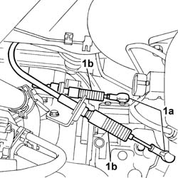
1. Remove the pivot joints (1a) for the gear selection and engagement flexible transmission cables (1b).
1. Unscrew bolts (1a) securing the bracket supporting gear selection and engagement cables (1b).
Place the cables and bracket to one side.
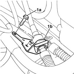
1. Unscrew bolts (1a) securing the bracket supporting gear selection and engagement cables (1b).
Place the cables and bracket to one side.
Raise the lift.
1. Undo the bolt (1a) fixing the exhaust manifold (1b).
2. Undo the nut (2a) fixing the ehxaust pipe coupling (2b) to the exhaust manifold.
3. Undo the lower nuts (3a) fastening the exhaust manifold heat shield (3b).
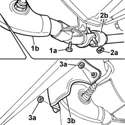
Raise the lift.
1. Undo the bolt (1a) fixing the exhaust manifold (1b).
2. Undo the nut (2a) fixing the ehxaust pipe coupling (2b) to the exhaust manifold.
3. Undo the lower nuts (3a) fastening the exhaust manifold heat shield (3b).
1. Remove the flexible mounting for the exhaust terminal in the wheel arch.
2. Remove the flexible mounting for the exhaust terminal.
3. Remove the flexible mounting for the exhaust pipe on the underbody.
4. Move the exhaust pipe assembly aside, releasing it from the exhaust manifold.
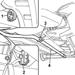
1. Remove the flexible mounting for the exhaust terminal in the wheel arch.
2. Remove the flexible mounting for the exhaust terminal.
3. Remove the flexible mounting for the exhaust pipe on the underbody.
4. Move the exhaust pipe assembly aside, releasing it from the exhaust manifold.
1. Remove the fastening clilp (1a) and release the brake fluid pipe (1b) from the suspension damper.
Work in the same way on both sides of the vehicle.
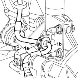
1. Remove the fastening clip (1a) and release the brake fluid pipe (1b) from the suspension damper.
Work in the same way on both sides of the vehicle.
1. Unscrew the retaining nut.
2. Fit the tool for releasing the steering track rod ends.
| Name | Country | |
|---|---|---|
| 2 | Extractor | 1.871.000.700 |
3. Release the steering track rod ends from the wheel hub.
4. Undo the fixing bolts (4a) and release the front steering knuckle (4b) from the shock absorber (4c).
Work in the same way on both sides of the vehicle.
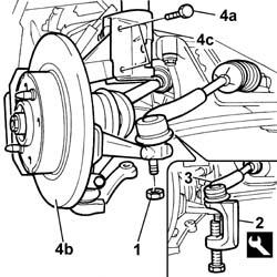
1. Unscrew the retaining nut.
2. Fit the tool for releasing the steering track rod ends.
| Name | Country | |
|---|---|---|
| 2 | Extractor | 1.871.000.700 |
3. Release the steering track rod ends from the wheel hub.
4. Undo the fixing bolts (4a) and release the front steering knuckle (4b) from the shock absorber (4c).
Work in the same way on both sides of the vehicle.
Vehicle left side.
1. Open the bands fastening the coupling boot.
2. Release the driveshaft from the differential side joint.
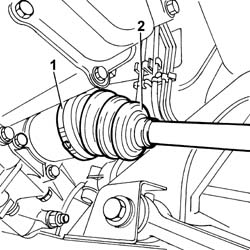
Vehicle left side.
1. Open the bands fastening the coupling boot.
2. Release the driveshaft from the differential side joint.
Work in the same way for the right side of the vehicle as described above for the left side, carrying out the following operation first:
1. Undo the fixing nut (1a) and the fixing bolts (1b) and move the wheel arch liner (1c) aside.
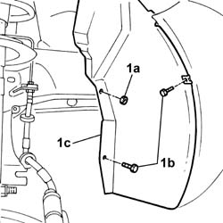
Work in the same way for the right side of the vehicle as described above for the left side, carrying out the following operation first:
1. Undo the fixing nut (1a) and the fixing bolts (1b) and move the wheel arch liner (1c) aside.
1. Undo the fixing bolts (1a) and remove the timing dust guard (1b).
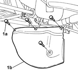
1. Undo the fixing bolts (1a) and remove the timing dust guard (1b).
1. Undo the bolt (1a) and (1b), then remove the lower reaction link (1c).
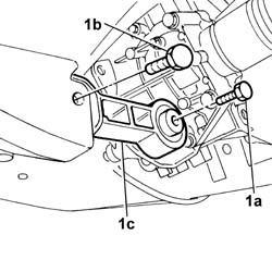
1. Undo the bolt (1a) and (1b), then remove the lower reaction link (1c).
Lower the vehicle.
1. Undo the upper fixing bolts (1a) and remove the exhaust manifold heat shield (1b).
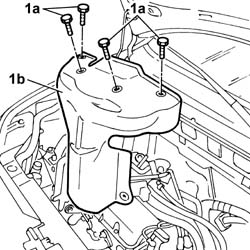
Lower the vehicle.
1. Undo the upper fixing bolts (1a) and remove the exhaust manifold heat shield (1b).
1. Open the fastening band (1a) and disconnect the upper cooling system hose (1b) from the radiator.
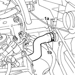
1. Open the fastening band (1a) and disconnect the upper cooling system hose (1b) from the radiator.
1. Undo the fixing nuts (1a) and remove the exhaust manifold (1b) complete with catalytic converter.
Remove the gasket.
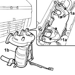
1. Undo the fixing nuts (1a) and remove the exhaust manifold (1b) complete with catalytic converter.
Remove the gasket.
1. Fasten the brackets to the cylinder block/crankcase for securing the chains later on.
Use a hydraulic lift with chains and hooks.
2. Anchor the hooks to the brackets.
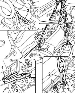
1. Fasten the brackets to the cylinder block/crankcase for securing the chains later on.
Use a hydraulic lift with chains and hooks.
2. Anchor the hooks to the brackets.
Lift the power unit slightly so that all cables are under the same strain.
1. Undo the bolt fixing the engine support to the gearbox side flexible mounting.
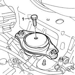
Lift the power unit slightly so that all cables are under the same strain.
1. Undo the bolt fixing the engine support to the gearbox side flexible mounting.
1. Unscrew nuts (1a) securing the flexible block (1b) to the timing end engine mount.
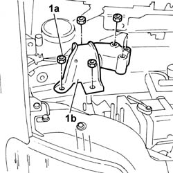
1. Unscrew nuts (1a) securing the flexible block (1b) to the timing end engine mount.
Carefully manoeuvre the hydraulic lift and remove the power unit moving it towards the engine compartment taking care not to damage surrounding parts.
Arrange the power unit on a platform.
Carefully manoeuvre the hydraulic lift and remove the power unit moving it towards the engine compartment taking care not to damage surrounding parts.
Arrange the power unit on a platform.
Refitting
Slowly manoeuvre the hydraulic lift to position the power unit inside the engine bay. Take care not to damage surrounding parts.
Place the flexible mounting in position and tighten the fixing nuts to torque.
| Fastening | Component | Ø | Value (daNm) | |
|---|---|---|---|---|
| Nut | FRONT RUBBER MOUNTS | M10 x 1.25 | 5 |
Tighten the bolt fixing the gearbox side flexible mounting to the engine support to torque.
| Fastening | Component | Ø | Value (daNm) | |
|---|---|---|---|---|
| Bolt | FRONT RUBBER MOUNTS | M12 x 1.25 | 8 |
Remove the hooks and the chains from the power unit.
Remove the mounting brackets fitted previously from the power unit.
Place the exhaust manifold complete with catalytic converter and gasket in position.
Tighten the nuts fixing the exhaust manifold to the cylinder head to torque.
| Fastening | Component | Ø | Value (daNm) | |
|---|---|---|---|---|
| Nut | EXHAUST MANIFOLD/S | M8 x 1.25 | (cylinder head) 2.5 |
Connect the upper cooling system hose to the engine cooling radiator and restore the fastening band.
Fit the heat shield on the exhaust manifold and tighten the fixing bolts to torque.
| Fastening | Component | Ø | Value (daNm) | |
|---|---|---|---|---|
| Bolt | PROTECTION COVER GUARDS/SUPPORTS | 0,9 - 1,2 |
Raise the car.
Fit the lower reaction rod in place and tighten the bolt fixing it to the gearbox to torque.
| Fastening | Component | Ø | Value (daNm) | |
|---|---|---|---|---|
| Bolt | REACTION ROD | M12 x 1.25 | (Gearbox side) 8 |
Tighten the bolt fixing the lower reaction bracket to the crossmember to torque.
| Fastening | Component | Ø | Value (daNm) | |
|---|---|---|---|---|
| Bolt | REACTION ROD | M12 x 1.25 | (Crossmember side) 8 |
Replace the grease contained inside the driveshafts and the differential housing.
Connect the driveshafts to the gearbox securing the boots with the bands.
| Type | Component | Name | Qty. | |
|---|---|---|---|---|
| Grease (g) | ENGINE ASSEMBLY | TUTELA MRM ZERO | 100 |
Position the front hub steering knuckle in the housing in the shock absorber and tighten the fixing bolts to torque.
| Fastening | Component | Ø | Value (daNm) | |
|---|---|---|---|---|
| Nut | FRONT HUB WITH BEARINGS | M10 x 1.25 | 7.5 |
Fit the steering track rod ends in place and tighten the fixing nut to torque.
| Fastening | Component | Ø | Value (daNm) | |
|---|---|---|---|---|
| Nut | ADJUSTABLE STEERING LINKS | M10 x 1.25 | 4 |
Fit the timing gear dust guard and tighten the fixing bolts.
Tighten the wheel arch liner bolts.
Secure the brake fluid pipe to the mounting.
Fit the exhaust pipe to the attachment on the exhaust manifold and secure it to the rubber mountings.
Tighten the nut fixing the metal collar for the flange joining the exhaust manifold to the centre section of the exhaust pipe.
| Fastening | Component | Ø | Value (daNm) | |
|---|---|---|---|---|
| Nut | EXHAUST MANIFOLD/S | M10 x 1.25 | 4 |
Fit the mounting bracket for the ball joints in place.
| Fastening | Component | Ø | Value (daNm) | |
|---|---|---|---|---|
| Bolt | GEAR ENGAGEMENT ASSEMBLY CABLE | M8 | 3 |
Fasten the ball joints for the gear selection and engagement flexible cables to the idler unit.
Fit the flexible transmission cables mounting bracket and tighten the fixing bolts.
Connect the clutch cable to the thrust bearing control lever and tighten the fixing nut.
Connect the electrical connection for the reversing sensor.
| Name | Connector | |
|---|---|---|
| Reversing lights switch | I20 |
Connect the earth lead to the gearbox and tighten the fixing nut.
| Name | Connector | |
|---|---|---|
| Battery earth on engine | C2 |
Fit the accelerator control cable in the housing in the throttle casing.
Connect the fuel vapour supply and collection pipes.
Connect the heater pipes to the housings in the bulkhead and renew the fastenings with the bands.
Connect the one-way valve to the brake servo.
Connect the electrical connection for the engine compartment junction unit and fit the protective cover.
| Name | Connector | |
|---|---|---|
| Front / engine coupling | D4 |
Connect the Lambda probe electrical connections.
| Name | Connector | |
|---|---|---|
| Lambda sensor on catalyzer | K17 |
| Name | Connector | |
|---|---|---|
| Lambda sensor on catalyzer -2 | K18 |
Fit the cooling system lower hose on the engine cooling radiator and renew the fastening band.
Fit the wheels in place and tighten the bolts to torque.
| Fastening | Component | Ø | Value (daNm) | |
|---|---|---|---|---|
| Bolt | FRONT WHEEL FIXING BOLT | M12 x 1.25 | (Steel rim) 8.6 |
Fit the air filter casing complete with cold air intake hose in position and tighten the fixing nuts.
Fit the battery cage complete with engine management control unit and tighten the fixing bolts.
Fit the battery cage cover.
Connect the electrical connectors for the engine management control unit.
| Name | Connector | |
|---|---|---|
| Engine management control unit | M10A |
| Name | Connector | |
|---|---|---|
| Engine management control unit | M10B |
Connect the earth lead.
| Name | Connector | |
|---|---|---|
| Engine management control unit | M10C |
Fit the battery in place and connect the wiring.
| Name | Connector | |
|---|---|---|
| Battery | A1B |
| Name | Connector | |
|---|---|---|
| Battery | A1A |
| Name | Connector | |
|---|---|---|
| Battery | A1E |
- 1820A14 clutch pedal - adjust travel
Refitting
Slowly manoeuvre the hydraulic lift to position the power unit inside the engine bay. Take care not to damage surrounding parts.
Place the flexible mounting in position and tighten the fixing nuts to torque.
| Fastening | Component | Ø | Value (daNm) | |
|---|---|---|---|---|
| Nut | FRONT RUBBER MOUNTS | M10 x 1.25 | 5 |
Tighten the bolt fixing the gearbox side flexible mounting to the engine support to torque.
| Fastening | Component | Ø | Value (daNm) | |
|---|---|---|---|---|
| Bolt | FRONT RUBBER MOUNTS | M12 x 1.25 | 8 |
Remove the hooks and the chains from the power unit.
Remove the mounting brackets fitted previously from the power unit.
Place the exhaust manifold complete with catalytic converter and gasket in position.
Tighten the nuts fixing the exhaust manifold to the cylinder head to torque.
| Fastening | Component | Ø | Value (daNm) | |
|---|---|---|---|---|
| Nut | EXHAUST MANIFOLD/S | M8 x 1.25 | (cylinder head) 2.5 |
Connect the upper cooling system hose to the engine cooling radiator and restore the fastening band.
Fit the heat shield on the exhaust manifold and tighten the fixing bolts to torque.
| Fastening | Component | Ø | Value (daNm) | |
|---|---|---|---|---|
| Bolt | PROTECTION COVER GUARDS/SUPPORTS | 0,9 - 1,2 |
Raise the car.
Fit the lower reaction rod in place and tighten the bolt fixing it to the gearbox to torque.
| Fastening | Component | Ø | Value (daNm) | |
|---|---|---|---|---|
| Bolt | REACTION ROD | M12 x 1.25 | (Gearbox side) 8 |
Tighten the bolt fixing the lower reaction bracket to the crossmember to torque.
| Fastening | Component | Ø | Value (daNm) | |
|---|---|---|---|---|
| Bolt | REACTION ROD | M12 x 1.25 | (Crossmember side) 8 |
Replace the grease contained inside the driveshafts and the differential housing.
Connect the driveshafts to the gearbox securing the boots with the bands.
| Type | Component | Name | Qty. | |
|---|---|---|---|---|
| Grease (g) | ENGINE ASSEMBLY | TUTELA MRM ZERO | 100 |
Position the front hub steering knuckle in the housing in the shock absorber and tighten the fixing bolts to torque.
| Fastening | Component | Ø | Value (daNm) | |
|---|---|---|---|---|
| Nut | FRONT HUB WITH BEARINGS | M10 x 1.25 | 7.5 |
Fit the steering track rod ends in place and tighten the fixing nut to torque.
| Fastening | Component | Ø | Value (daNm) | |
|---|---|---|---|---|
| Nut | ADJUSTABLE STEERING LINKS | M10 x 1.25 | 4 |
Fit the timing gear dust guard and tighten the fixing bolts.
Tighten the wheel arch liner bolts.
Secure the brake fluid pipe to the mounting.
Fit the exhaust pipe to the attachment on the exhaust manifold and secure it to the rubber mountings.
Tighten the nut fixing the metal collar for the flange joining the exhaust manifold to the centre section of the exhaust pipe.
| Fastening | Component | Ø | Value (daNm) | |
|---|---|---|---|---|
| Nut | EXHAUST MANIFOLD/S | M10 x 1.25 | 4 |
Fit the mounting bracket for the ball joints in place.
| Fastening | Component | Ø | Value (daNm) | |
|---|---|---|---|---|
| Bolt | GEAR ENGAGEMENT ASSEMBLY CABLE | M8 | 3 |
Fasten the ball joints for the gear selection and engagement flexible cables to the idler unit.
Fit the flexible transmission cables mounting bracket and tighten the fixing bolts.
Connect the clutch cable to the thrust bearing control lever and tighten the fixing nut.
Connect the electrical connection for the reversing sensor.
| Name | Connector | |
|---|---|---|
| Reversing lights switch | I20 |
Connect the earth lead to the gearbox and tighten the fixing nut.
| Name | Connector | |
|---|---|---|
| Battery earth on engine | C2 |
Fit the accelerator control cable in the housing in the throttle body.
Connect the fuel vapour supply and collection pipes.
Connect the heater pipes to the housings in the bulkhead and renew the fastenings with the bands.
Connect the one-way valve to the brake servo.
Connect the electrical connection for the engine compartment junction unit and fit the protective cover.
| Name | Connector | |
|---|---|---|
| Front / engine coupling | D4 |
Connect the Lambda probe electrical connections.
| Name | Connector | |
|---|---|---|
| Lambda sensor on catalyzer | K17 |
| Name | Connector | |
|---|---|---|
| Lambda sensor on catalyzer -2 | K18 |
Fit the cooling system lower hose on the engine cooling radiator and renew the fastening band.
Fit the wheels in place and tighten the bolts to torque.
| Fastening | Component | Ø | Value (daNm) | |
|---|---|---|---|---|
| Bolt | FRONT WHEEL FIXING BOLT | M12 x 1.25 | (Steel rim) 8.6 |
Fit the air filter casing complete with cold air intake hose in position and tighten the fixing nuts.
Fit the battery cage complete with engine management control unit and tighten the fixing bolts.
Fit the battery cage cover.
Connect the electrical connectors for the engine management control unit.
| Name | Connector | |
|---|---|---|
| Engine management control unit | M10A |
| Name | Connector | |
|---|---|---|
| Engine management control unit | M10B |
Connect the earth lead.
| Name | Connector | |
|---|---|---|
| Engine management control unit | M10C |
Fit the battery in place and connect the wiring.
| Name | Connector | |
|---|---|---|
| Battery | A1B |
| Name | Connector | |
|---|---|---|
| Battery | A1A |
| Name | Connector | |
|---|---|---|
| Battery | A1E |
Parts & tools for this job Staging For 2003 Fiat Panda
- PARTClutch kitSearch: Fiat Panda 2003 clutch kit
- TOOLClutch alignment toolSearch: clutch alignment tool
- FLUIDGear oilSearch: Fiat Panda manual gearbox oil
Links open Amazon search results in a new tab. As an Amazon Associate I earn from qualifying purchases.