
Gas circuit multi point injection
- Make
- Fiat
- Model
- Multipla Factory Service Manual
- Year
- 1998–2010
- Section
- Gas circuit › Gas circuit multi point injection
GAS CIRCUIT MULTI POINT INJECTION
The Marelli IAW 4GF.2M system belongs to the category of systems integrated with:
- inductive discharge digital electronic ignition
- static distribution
- sequential, phased electronic injection (1-3-4-2).
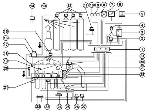
1, Engine control unit
2, Injection system relay
3, Battery
4, Ignition switch
5, Engine coolant overheating warning light
6, Injection system failure warning light
7, Signal for rev counter
8, Fiat CODE connection
9, Diagnostic equipment connection
10, Climate control connection
11, Canister solenoid valve relay feed
12, Canister solenoid valves
13, Methane canisters
14, Inertia switch
15, Lambda probe
16, Methane pressure sensor
17, Methane pressure reduction unit
18, Engine timing sensor
19, Air temperature and pressure sensor
20, Engine rpm and TDC sensor
21, Methane supply manifold with injectors
22, Injector relay feed
23, Detonation sensor
24, Radiator fan
25, Engine coolant temperature sensor
26, Radiator fan high speed relay feed
27, Radiator fan low speed relay feed
28, Ignition coils
29, Vehicle speed sensor
30, Engine idle speed actuator
31, Butterfly valve position sensor
The system operates in the same way as described for the bipower version, with the exception of the functions relating the operation of the electric fuel pump and the management of the fuel vapour recirculation which are peculiar to the petrol system.
There follows a description of the specific components for the methane injection injection: for anything not dealt with, refer to chapter 1056B.
DIAGRAM OF INPUT/OUTPUT INFORMATION FROM THE CONTROL UNIT
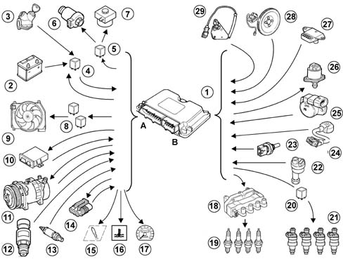
1, Engine control unit
2, Battery
3, Ignition switch
4, Injection system relay
5, Canister solenoid valves relay feed
6, Canister solenoid valves
7, Methane pressure reduction solenoid valve
8, Radiator fan relay feed
9, Radiator fan
10, Fiat CODE connection
11, Climate control connection
12, Methane pressure sensor
13, Lambda sensor
14, Diagnostic equipment connection
15, Injection system failure warning light
16, Engine coolant overheating warning light
17, Signal for rev counter
18, Ignition coil
19, Spark plugs
20, Injector relay feed
21, Methane injectors
22, Vehicle speed sensor
23, Engine coolant temperature sensor
24, Detonation sensor
25, Butterfly valve position sensor
26, Engine idle speed actuator
27, Air temperature and pressure sensor
28, Engine rpm and TDC sensor
29, Engine timing sensor
CONTROL UNIT PIN OUT
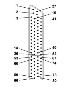
1, N.c.
2, N.c.
3, N.c.
4, Rev counter signal
5, N.c.
6, N.c.
7, N.c.
8, N.c.
9, Lambda sensor (negative)
10, N.c.
11, N.c.
12, N.c.
13, Fiat CODE two-way line
14, Fan high speed relay operation
15, Low relay operation
16, N.c.
17, Engine coolant overheating warning light
18, N.c.
19, N.c.
20, Lambda sensor (positive)
21, N.c.
22, N.c.
23, N.c.
24, N.c.
25, Diagnostic socket (line k)
26, Injection system failure warning light
27, Power control unit earth
28, Power control unit earth
29, Control unit supply (+12V Batt.)
30, Methane pressure sensor supply 5V
31, N.c.
32, N.c.
33, Methane pressure sensor earth
34, N.c.
35, Request to engage fan low speed
36, N.c.
37, N.c.
38, N.c.
39, N.c.
40, Fan low speed relay operation
41, Air conditioning compressor relay
42, N.c.
43, N.c.
44, Lambda sensor cable screening
45, N.c.
46, Gas pressure signal
47, Key on signal
48, Air conditioning engagement request
49, N.c.
50, Vehicle speed signal
51, N.c.
52, N.c.
53, Rpm sensor (positive)
54, Sensor earth
55, Intake air temperature signal
56, Detonation sensor (positive)
57, Stepper phase C operation
58, Stepper phase D operatoin
59, Ignition coils (cylinders 1-4)
60, Butterfly valve position sensor supply +5V
61, N.c.
62, Engine coolant temperature sensor (positive)
63, Detonation sensor cable screening
64, Stepper phase B operation
65, Stepper phase A operation
66, Ignition coils (cylinders 2-3)
67, Rpm sensor (negative)
68, Absolute pressure and timing sensor supply
69, Timing sensor signal
70, Detonation sensor (negative)
71, Injector for cylinder no. 1
72, Injector for cylinder no. 4
73, N.c.
74, N.c.
75, Pressure sensor signal
76, Butterfly valve position signal
77, Rpm sensor cables screening
78, Injector for cylinder no. 3
79, Injector for cylinder no. 2
80, N.c.
METHANE INJECTORS
Construction features
The specific methane injectors are the sonic type.
The main difference between these injectors and those which operate on petrol lies in the fact that they have a larger nozzle for the exit of the methane and they receive a considerably higher pressure (9 ± 1 bar). As a result, the quantity of methane injected only depends on the opening time of the injector (injection time) which is established by the electronic control unit.
The injectors are fixed by the methane distribution manifold, which presses them into their seats in the inlet ducts.
They are also secured to the methane distribution manifold by means of safety clips. Two rubber seals (1) and (2) ensure the sealat the inlet manifold and the methane distribution manifold.
The methane is supplied at the top (3) of the injector (top feed); the connector for the operation of the injector engages in the seat (4).
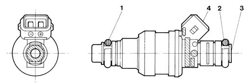
Operation
The control logic for the injectors is the sequential, phased type, in other words the four injectors are operated individually according to the engine cylinder inlet sequence, whilst the supply for each cylinder can already start when the inlet stroke has already started.
METHANE MANIFOLD
Construction features
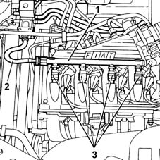
The methane distribution manifold (1) is fixed at the top part of the intake manifold. It receives methane at low pressure from the flexible pipe (2) which acts as a connection with the pressure reduction unit and distributes it to the four injectors (3).
METHANE PRESSURE SENSOR
The pressure sensor (1) is fitted on the pressure reduction unit (2), at the high pressure line (3) intake.
Construction features
It is a capacitive type sensor (where the sensitive element is made from two gold-plated ceramic discs) which contains the signal conditioning circuit.
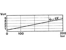
It receives a supply of 5V.
The measurement of the methane pressure at the high pressure line is designed to:
- indicate the quantity of methane in the canister (fuel gauge)
- provide an indication to the control unit for automatically switching the supply from methane to petrol if the methane pressure is too low (below 15 bar)
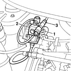
Supply: pin 30
Earth: pin 33
Signal: pin 46
PETROL/METHANE SWITCH
The system has a petrol-methane selector button which operates in the following way:
- button pressed, petrol operation
- button not pressed, methane operation, with the exception of certain particular situations (initial starting after methane supply, methane has run out, faults which require a switch to petrol).
Parts & tools for this job Staging For 1998 Fiat Multipla
- TOOLDigital multimeterSearch: automotive digital multimeter
- PARTAssorted fuse kitSearch: car fuse assortment kit
- TOOLWire crimper and connector kitSearch: wire crimper connector kit
Links open Amazon search results in a new tab. As an Amazon Associate I earn from qualifying purchases.