
Vacuum air circuit
- Make
- Fiat
- Model
- Multipla Factory Service Manual
- Year
- 1998–2010
- Section
- Engine air supply circuit › Vacuum air circuit
Vacuum air circuit
The air intake circuit consists of various components which ensure that the air flow required by the engine in the various operating conditions is correctly directed.
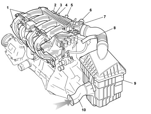
1, Inlet manifold
2, Intake air pressure and temperature sensor (See subassembly 1056 PETROL INJECTION SYSTEM)
3, Intake for fuel anti-evaporation system (See subassembly 1080 EXHAUST EMISSION CONTROL SYSTEM)
4, Gas intake from engine crankcase (blow-by) for recirculating exhaust gases at idle speed (See subassembly 1080 EXHAUST EMISSION CONTROL SYSTEM)
5, Intake for brake servo
6, Engine idle speed actuator (See subassembly 1056 PETROL INJECTION SYSTEM)
7, Butterfly casing (See subassembly 1056 PETROL INJECTION SYSTEM)
8, Main gas intake from engine crankcase (See subassembly 1080 EXHAUST EMISSION CONTROL SYSTEM)
9, Air filter
10, Intake vent
Parts & tools for this job Staging For 1998 Fiat Multipla
- TOOLDigital multimeterSearch: automotive digital multimeter
- PARTAssorted fuse kitSearch: car fuse assortment kit
- TOOLWire crimper and connector kitSearch: wire crimper connector kit
Links open Amazon search results in a new tab. As an Amazon Associate I earn from qualifying purchases.