
Introduction - timing system
- Make
- Alfa Romeo
- Model
- 159 Factory Service Manual
- Year
- 2005–2011
- Section
- Timing system › Introduction - timing system
INTRODUCTION - TIMING SYSTEM
SPECIFICATIONS
Chain-driven twin overhead camshaft timing system, four valves per cylinder, hydraulic tappets with roller-driven levers, vane-type continuous variable valve driving system on both camshafts.
Vane-type continuous variable valve timing
The vane-type variable valve timing system allow the phase to be varied continuously on both shafts. The angular position is given by the rotor-stator drive inside the vvt. The intake side vvt allows a camshaft angle of no less than 30°, while the exhaust side vvt allows rotation ofi 25°. The engine control unit determines cam position by means of sensors on the camshaft and crankshaft.
It consists of a stator that is made to turn with the crankshaft by means of a chain and a rotor connected directly to the camshaft that may move in relation to the stator.
The rotor and stator may be offset by using an electrohydraulic valve that allows the vanes between the them to be filled with fluid.
The solenoid consists of a needle cursor that is moved into three different positions via the electromagnetic induction of a solenoid.
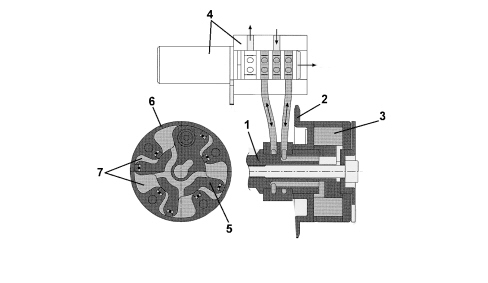
1. Camshaft
2. Toothed wheel
3. Variable valve timing
4. Four-way solenoid
5. Rotor
6. Stator
7. Gaps
These different cursor positions create three different situations:
1) the fluid flows into the space between the stator and rotor so that the camshaft is offset anticlockwise;
2) the reverse situation to the above creates clockwise rotation;
3) retaining the fluid present in both gaps fixes the relative position.
A mechanical system (pin lock) on the variable valve timing does not allow it to operate until a given pressure is reached. Beyond this threshold, the system is made to operate by following optimum setpoints set in the control unit.
The benefits of this variable valve timing system are not perceptible in absolute terms, i.e. the maximum torque and power values are not higher than those of a system not equipped with variable valve timing but the engine is more vigorous throughout the rpm range.
Technical specifications
Each of the two cylinder heads houses two camshafts, one for the opening of the inlet valves and one for the opening of the exhaust valves.
The camshafts are supported by four bearings fitted on the cylinder head. The camshaft for the left cylinder head is also supported by another bearing due to the connection with the shaft used for activating the high pressure fuel pump; the front (timing side) bearing also carries out the task of controlling the camshaft thrust.
Each of the four camshafts is connected by the respective "continuous" type phase transformer.
Components
Camshafts
The four camshafts are made from cast iron with a superficial treatment of the cams.
The active part of the cams is produced with a profile with a 250 degree angle for the inlet valves and 254 degree angle for the exhaust valves; the valve lift is 11 mm for both the inlet valves and the exhaust valves.
The phase transformers are fitted on the front of the camshafts and there are ports for supplying the oil to the phase transformer actuators.
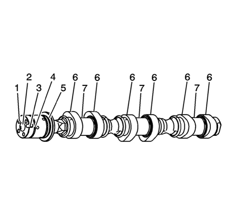
1. Oil supply ports for phase transformer actuators
2. Threaded port
3. Phase transformer actuator position reference
4. Seal housing
5. Shoulder surface
6. Cams
7. Bearings
Rocker arms and tappets
The rocker arm is the type with a finger and roller; this system makes it possible to minimize the loss in output due to the operation of the rocker arms by the camshaft in as far as the relative movement between the cam and roller is a rolling movement and not a sliding movement as is the case in other systems.
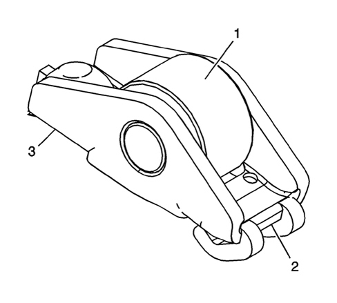
1. Roller
2. Valve rocker arm contact
3. Tappet rocker arm contact
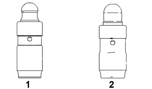
The tappets are the hydraulic type and continuously ensure the correct operating contact between the components controlling the valve lift; the tappets for the exhaust valves (1) and inlet valves (2) are different heights and should not be mixed up, the diameter of both tappets, on the other hand, is the same.
Variable timing system
The continuous variable timing system controls and alters the timing diagram in relation to the different operating conditions to ensure optimum engine behaviour in terms of an increase in performance and reduction in consumption and emissions.
Basically the advantages should not be seen in terms of a simple increase in the maximum torque and maximum power, but as a gain in powerfulness, fullness and prompt responsiveness throughout the entire engine operating speed and load range.
There are four transformers for this engine, one for each camshaft; they are capable of altering the cam angle during the operation of the engine based on the usage conditions. There are therefore four control solenoid valves, through which the engine management control unit regulates the flow of oil inside the actuator compartments to allow the rotation of the camshafts in relation to the gears controlled by the secondary timing chains.
The phase transformers allows the continuous rotation of the camshafts at 50 degrees.
The engine management control unit determines and controls the position of the cam through sensors on the camshafts and the crankshaft.
Principle diagram
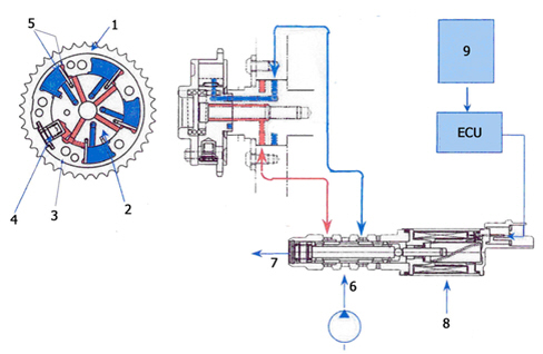
1. Camshaft toothed drive pulley
2. Rotor
3. Stator
4. Locking pin
5. Compartments
6. Oil supply
7. Oil drain
8. Solenoid valve
9. Input signals from sensors
Operation
The actuator consists of a stator rotated by the ring gear which it forms one piece with controlled by the secondary timing chain and a rotor connected directly to the camshaft which can move in relation to the actual stator. The rotor and stator may become offset by sending oil which, flowing through ducts controlled by the solenoid valve operated by the control unit, fills the compartments between the internal profiles of the actual stator and the rotor. This produces the rotation in both directions depending on the "distribution of the oil" by the control unit by means of the solenoid control valve (1).
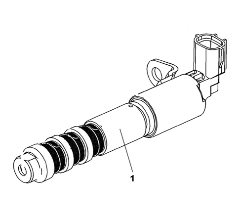
The solenoid valve is made up of a needle cursor that is moved in three different poisitions through the electromagnetic induction of a solenoid; in this way each of the two types of compartment for the transformer may be placed in contact either with the oil supply duct or the drainage duct depending on the rotation. Obviously, in order to allow the movement, when one compartment is in contact with a duct, the other should be in contact with the other duct and viceversa, to allow the flow of oil; the different positions of the cursor lead to three distinct situations:
1) the oil flows into the red compartment and out of the other (blue) so that the camshaft is offset in an anti-clockwise direction;
2) the oil flows into the blue compartment and out of the other (red) so that the camshaft is offset in a clockwise direction;
3) the oil in the two compartments is stopped so that the position between the stator and the rotor is maintained. In this situation the position of the solenoid needle ensures that the two types of transformer compartments are insulated and are not in contact with either the supply duct or the oil drainage duct.
With the engine idling, both camshafts are in the "default" or "basic fitting" position which is maintained thanks to an internal pin that locks the rotation of the shaft (rotor) in relation to the timing gear (stator) in the basic position. In this situation the exhaust camshafts are completely advanced and the inlet camshafts completely delayed and remain like this during starting; this timing configuration guarantees the minimum crossover between the inlet and exhaust valves.
The pins that lock the camshafts in the basic position ensure that they are in the correct position on starting and that there is no noise due to the uncontrolled rotation of the rotor in relation to the stator. To allow the movement of the phase transformer a certain operating pressure must be reached in order to release the pin locking the transformer in the basic position and allowing movement.
Depending on the engine position, it is possible from the basic position to control the advance of the inlet camshafts and the delay of the exhaust camshafts within a maximum rotation range of 50 degrees for each shaft; what is of fundamental importance is that this system makes it possible to control all the intermediate positions for the shafts within the above mentioned range so that the best engine working conditions can be produced for all speed and load conditions.
Variable valve timing actuator
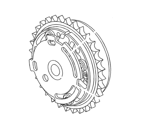
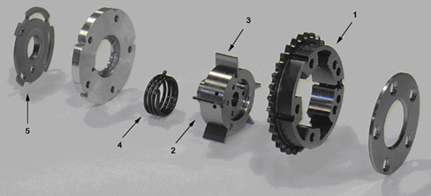
1. Stator
2. Rotor
3. Vanes
4. Spring
5. Flywheel
The above diagram shows the stator with the ring gear and the rotor with the camshaft. The rotor is the vane type with ports that supply the compartments on either side of each of the four vanes; a fifth vane acts as a lock-up locking the actuator in the normal fitting position.
The lock-up is only released when the oil that passes through a port pushes the lock-up (pin) vane towards the edge of the stator reaches the operating pressure releasing the rotor from the stator. A spring guarantees the pre-loading of the rotation between the rotor and the stator cover.
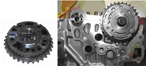
The housing for the camshaft with the oil arrival ports can be seen below; a second set of openings is found inside the main shaft port where the shaft fixing bolt is found.
The two sets of ports supply the compartments on either side of the four vanes separately.
Timing diagram variation
Thanks to the intervention of the phase transformers, the timing diagram can be altered; in particular, the opening advance for the inlet valves can move inside the area defined by the line A and the line A'', whilst the closing delay for the exhaust valves can move inside the area definied by the line B and the line B''.
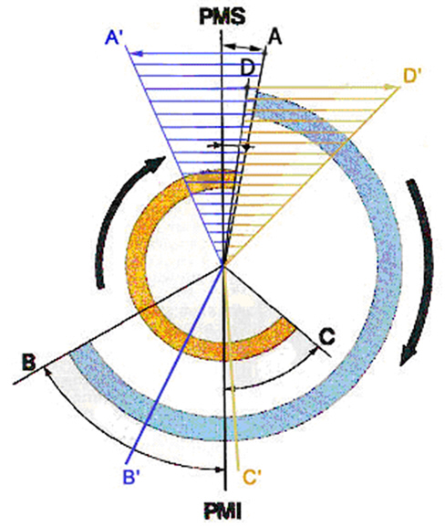
A. Inlet shaft basic fitting position (completely delayed)
B. Exhaust shaft basic fitting position (completely advanced)
A''. Maximum rotation in relation to inlet shaft position
B’. Maximum rotation in relation to exhaust shaft position
The action of the phase transformers is therefore principally understood as controlling the opening advance of the inlet valves and the closing delay of the exhaust valves. Obviously the variation in the opening advance of the inlet valves also produces a variation in their closing point in the same way as the variation in the closing delay of the exhaust valves also produces a variation in the opening point.
The maps used for the management of the timing diagram are a compromise between the opening advance and closing delay for both the inle and exhaust valves in terms of ensuring optimum consumption, performance and emissions.
SPECIFICATIONS
Toothed belt-driven twin overhead camshaft timing system, four valves per cylinder, mechanical tappets, vane-type continuous variable valve driving system on both camshafts.
The benefits of a timing system like this are a reduction in emissions and consumption. The following are possible depending on the different load conditions:
- reduced loads
a minimum valve crossover is set because in this case the high vacuum in the intake manifold causes the reflux of a large quantity of exhaust gases with a minimum crossover.
As a result, the engine runs smoothly when idling.
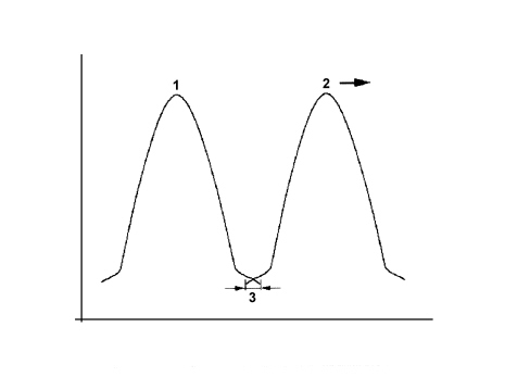
1. Inlet valve lift
2. Exhaust valve lift, moved in an "advance" direction
3. Minimum valve crossover
- medium-low loads
the valve crossovers set are greater because in these conditions the engine supports a larger quantity of residual gases. This produces a drastic reduction in nitrogen oxide emissions.
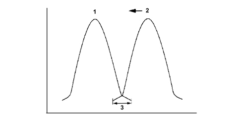
1. Inlet valve lift
2. Exhaust valve lift, moved in an "advance" direction
3. Maximum valve crossover
- heavy load
the crossover of the valves is reduced to a minimum because maximum cylinder refilling with a fresh mixture is desired as a result of the engine''s increased requirements.
Vane type continuous phase transformer
The vane-type variable valve timing system allow the phase to be varied continuously on both shafts. The angular position is given by the rotor-stator drive inside the transformer. The intake side phase transformer allows a camshaft angle of no less than 60°, while the exhaust side phase transformer allows rotation of 45°. The engine management control unit determines the position of the cam through sensors on the camshafts and the crankshaft.
The stator is made to turn with the crankshaft by means of a belt whilst the rotor is connected directly to the camshaft that may move in relation to the stator.
The rotor and stator may be offset by using an electrohydraulic valve that allows the vanes between the them to be filled with fluid.
The camshaft adjustment system comprises the following components:
- Adjustment unit
- Solenoid valves
- Route of the fluid towards the solenoid valve
- Route of the fluid from the solenoid valve chamber A of the camshaft regulator
- Route of the fluid from the solenoid valve chamber B of the camshaft regulator
- Camshaft phonic wheel with timing sensor
- Camshaft phonic wheel with rpm and T.D.C. sensor
- Engine management control unit.
Electrical components for camshaft adjustment
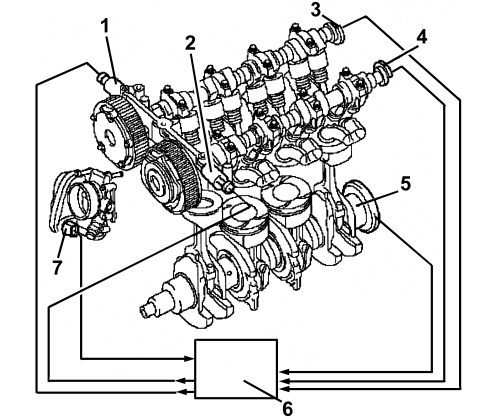
1. Hydraulic control valve electromagnetically activated by the inlet camshaft
2. Hydraulic control valve electromagnetically activated by the exhaust camshaft
3. Inlet side timing sensor
4. Exhaust side timing sensor
5. Rpm and T.D.C. sensor
6. Engine management control unit
7. Throttle valve actuator
Mechanical components for the camshaft adjustment
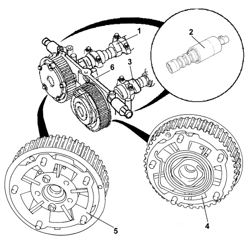
1. Inlet camshaft
2. Camshaft adjustment valve
3. Exhaust camshaft
4. Exhaust camshaft regulator
5. Inlet camshaft regulator
6. Camshaft bearings support
Operation
The engine oil is directed via a special duct directly from the oil pump, through the head, towards the camshaft bearings support (3). There is a solenoid valve for each camshaft on the camshaft bearings support to drain and refill chambers A and B for the respective camshaft regulator or for closing all the connections with a perfect seal to fix the relative position of the camshaft.
The flow of oil towards chamber B of the camshaft regulator is directed along the collar (6) of the fastening bolt (9). The flow of oil towards chamber A of the camshaft regulator is directed via the separated, decentralised, axially positioned openings (2). When the oil chambers of the inlet side or exhaust side camshaft regulator are refilled or drained, the angular position of the shafts is altered.
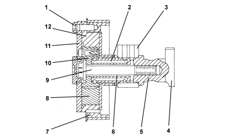
1. Bolt securing camshaft regulator cover
2. Oil duct towards chamber A of the camshaft regulator
3. Camshaft bearings support
4. Cam
5. Camshaft
6. Oil duct towards chamber B of the camshaft regulator
7. Gear driven by toothed belt
8. Partition between chambers A and B
9. Bolt securing camshaft regulator
10. Rotor
11. Camshaft regulator cover
12. Stator
Inlet camshaft regulator
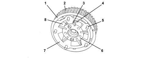
1. Inlet camshaft regulator (outer) edge
2. Gear driven by toothed belt
3. Chamber A refilling and draining port
4. Chamber B refilling and draining port
5. Bolt securing camshaft regulator cover
6. Rotor, connected to camshaft
7. Stator, hydraulically adjustable
8. Partition between chamber A and chamber B
Exhaust camshaft regulator
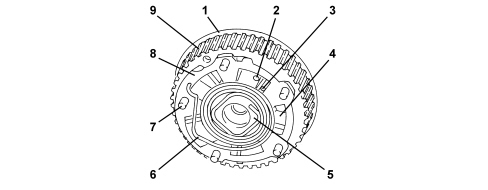
1. Exhaust camshaft regulator (inner) edge
2. Chamber A refilling and draining port
3. Chamber B refilling and draining port
4. Partition between chamber A and chamber B
5. Rotor, connected to camshaft
6. Return spring, returns the stator to the initial position when no oil pressure is applied
7. Bolt securing camshaft regulator cover
8. Stator, hydraulically adjustable
9. Gear driven by toothed belt
The solenoid valve comprises a needle cursor which is moved into 3 different positions through the electromagnetic induction of a solenoid in order to either refill or drain chambers A and B. The solenoid valve is controlled by the engine management control unit.
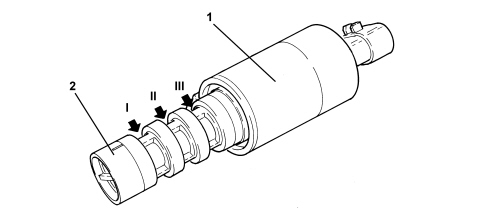
1. Solenoid
2. Needle cursor with port for connecting the splining (I) and (II) and the axial port for connecting the splining (III) with the pressure free return
Diagram showing structure of hydraulic valve
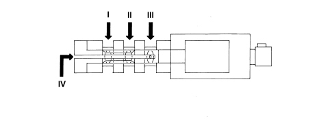
The splining (II) is connected internally with the splining (I) as a result of which the oil supply duct can be switched only once to suply chamber A or chamber B.
The splining (III) is only designed for the pressure free return (IV) from chamber B.
The 3 different positions for the cursor are illustrated below
1. The supply (II) is always connected to the pressurized oil supply. Thanks to the position of the valves illustrated in the diagram, the pressurized supply is connected with the oil directed towards chamber A in the camshaft regulator. Chamber B of the camshaft regulator is simultaneously drained through the pressure free return (III) and (IV).
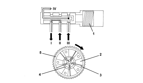
1. Hydraulic valve solenoid
2. Chamber A
3. Chamber B
4. Rotor
5. Stator
2. The supply (II) is always connected to the pressurized oil supply. Thanks to the position of the valves illustrated in the diagram, the pressurized supply is connected with the oil directed towards chamber B in the camshaft regulator. Chamber A of the camshaft regulator is simultaneously drained through the pressure free return (IV).
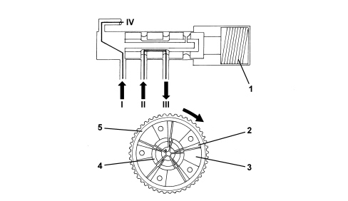
1. Hydraulic valve solenoid
2. Chamber A
3. Chamber B
4. Rotor
5. Stator
3. All the supply and return openings are closed and sealed through the position of the valves shown in the diagram. It is not possible to introduce oil into chamber A or B of the camshaft regulator or drain either of the two chambers. In this way, the position set between the stator and the rotor remains unchanged (the relative position is fixed).
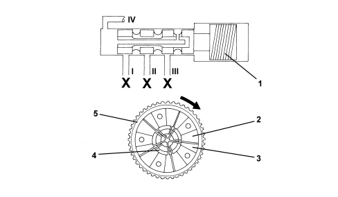
1. Hydraulic valve solenoid
2. Chamber A
3. Chamber B
4. Rotor
5. Stator
Parts & tools for this job Staging For 2005 Alfa Romeo 159
- PARTEngine gasket setSearch: Alfa Romeo 159 2005 engine gasket set
- TOOLTorque wrenchSearch: 3/8 inch torque wrench
- TOOLFeeler gauge setSearch: feeler gauge set
Links open Amazon search results in a new tab. As an Amazon Associate I earn from qualifying purchases.