
Exhaust emission control system
- Make
- Alfa Romeo
- Model
- 159 Factory Service Manual
- Year
- 2005–2011
- Section
- Emission control system › Exhaust emission control system
EXHAUST EMISSION CONTROL SYSTEM
DESCRIPTION OF COMPONENTS
CATALYTIC CONVERTER
Specifications
The catalytic converter is a post-treatment device for oxidizing the CO, HC and particles transforming them into carbon dioxide (CO2) and water vapour (H20).
The catalytic converter consists of a ceramic, honeycomb structure (1) with cells impregnated with platinum (2) which catalyzes the oxidation reactions.
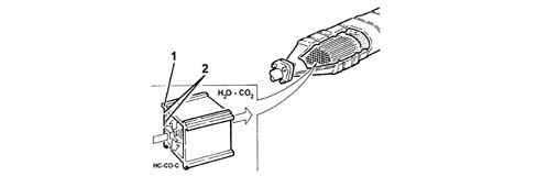
Operation
The exhaust gases passing through the cells heat the catalyzer triggering off the conversion of the pollutants into inert compounds.
The oxidizing chemical reaction of the CO, HC and particles is effective at temperatures of between 200 and 350°C.
In effect, above 350°C the sulphur contained in the diesel fuel starts to oxidize producing sulphur dioxide and sulphur trioxide.
DPF SYSTEM (Diesel Particulate Filter)
This is a mechanical filter that "traps" the carbon particles (particulate) and the engine oil ashes in the exhaust gases in diesel engines.
The action of the DPR makes it possible to keep carbon particle levels by around 90% in line with Euro 4 and 5 regulations.
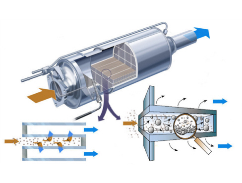
The operation of the DPF system is managed by the engine injection control unit by means of suitable strategies. In addition to the actual filter the DPF system comprises an exhaust gas temperature sensor and a differential pressure sensor.
The differential pressure sensor measures the pressure of the exhaust gases upstream and downstream of the filter, by means of special pipes, signalling the gradual accumulation of particulate to the control unit. The particulate accumulation process and the relative increase in the pressure of the exhaust gases inside the filter depends on the engine load, the weight of the vehicle and the engine capacity and power. Therefore the particulate needs to be removed on a regular basis, regenerating the filter following a procedure that makes use of multiple injections to increase the temperature of the exhaust gases (about 600°C) and burn the particulate. The regeneration procedure is controlled by the injection control unit which acts: on the metering of the fuel (up to five injections in the same engine cycle per cylinder) and on the control of the air (E.G.R. and supercharging pressure).
The regeneration phase takes place over a few minutes and does not affect the continuity of the torque supplied by the engine in terms of normal operation.
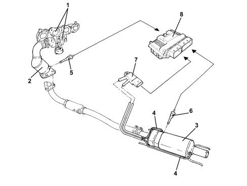
1. Turbocharger-exhaust manifold assembly
2. Catalytic converter
3. Filter
4. Exhaust gas pressure intake
5. Exhaust gas temperature sensor downstream of the catalyzer
6. Exhaust gas temperature sensor downstream of the filter
7. Differential pressure sensor
8. Injection control unit
DESCRIPTION OF COMPONENTS
CATALYTIC CONVERTER
Specifications
The catalytic converter is a post-treatment device for oxidizing the CO, HC and particles transforming them into carbon dioxide (CO2) and water vapour (H20).
The catalytic converter consists of a ceramic, honeycomb structure (1) with cells impregnated with platinum (2) which catalyzes the oxidation reactions.
Operation
The exhaust gases passing through the cells heat the catalyzer triggering off the conversion of the pollutants into inert compounds.
The oxidizing chemical reaction of the CO, HC and particles is effective at temperatures of between 200 and 350°C.
In effect, above 350°C the sulphur contained in the diesel fuel starts to oxidize producing sulphur dioxide and sulphur trioxide.
DPF SYSTEM (Diesel Particulate Filter)
This is a mechanical filter that "traps" the carbon particles (particulate) and the engine oil ashes in the exhaust gases in diesel engines.
The action of the DPR makes it possible to keep carbon particle levels by around 90% in line with Euro 4 and 5 regulations.
The operation of the DPF system is managed by the engine injection control unit by means of suitable strategies. In addition to the actual filter the DPF system comprises an exhaust gas temperature sensor and a differential pressure sensor.
The differential pressure sensor measures the pressure of the exhaust gases upstream and downstream of the filter, by means of special pipes, signalling the gradual accumulation of particulate to the control unit. The particulate accumulation process and the relative increase in the pressure of the exhaust gases inside the filter depends on the engine load, the weight of the vehicle and the engine capacity and power. Therefore the particulate needs to be removed on a regular basis, regenerating the filter following a procedure that makes use of multiple injections to increase the temperature of the exhaust gases (about 600°C) and burn the particulate. The regeneration procedure is controlled by the injection control unit which acts: on the metering of the fuel (up to five injections in the same engine cycle per cylinder) and on the control of the air (E.G.R. and supercharging pressure).
The regeneration phase takes place over a few minutes and does not affect the continuity of the torque supplied by the engine in terms of normal operation.
1. Turbocharger-exhaust manifold assembly
2. Catalytic converter
3. Filter
4. Exhaust gas pressure intake
5. Exhaust gas temperature sensor downstream of the catalyzer
6. Exhaust gas temperature sensor downstream of the filter
7. Differential pressure sensor
8. Injection control unit
DESCRIPTION OF COMPONENTS
CATALYTIC CONVERTER
Specifications
The catalytic converter is a post-treatment device for oxidizing the CO, HC and particles transforming them into carbon dioxide (CO2) and water vapour (H20).
The catalytic converter consists of a ceramic, honeycomb structure (1) with cells impregnated with platinum (2) which catalyzes the oxidation reactions.
Operation
The exhaust gases passing through the cells heat the catalyzer triggering off the conversion of the pollutants into inert compounds.
The oxidizing chemical reaction of the CO, HC and particles is effective at temperatures of between 200 and 350°C.
In effect, above 350°C the sulphur contained in the diesel fuel starts to oxidize producing sulphur dioxide and sulphur trioxide.
DPF SYSTEM (Diesel Particulate Filter)
This is a mechanical filter that "traps" the carbon particles (particulate) and the engine oil ashes in diesel engine exhaust gases.
The action of the DPF makes it possible to keep the level of carbon particles down by around 90% in line with Euro 4 and 5 regulations.
The operation of the DPF system is managed by the injection control unit by means of special strategies. In addition to the filter the DPF system comprises an exhaust gas temperature sensor and a differential pressure sensor.
The differential pressure sensor measures the pressure of the exhaust gases upstream and downstream of the filter, by means of special pipes, signalling the gradual accumulation of particulate to the control unit. The particulate accumulation process and increase in the pressure of the exhaust gases inside the filter depends on the engine load, the weight of the vehicle, the engine capacity and power. Therefore the occasional removal of the particulate is necessary, regenerating the filter by means of a procedure that makes use of multiple injections to increase the temperature of the exhaust gases (about 600°C) and consequently burn the particulate. The regeneration procedure is controlled by the injection control unit which acts: on the metering of the fuel (up to five injections in the same engine cycle per cylinder) and on the control of the air (E.G.R. and supercharging pressure).
The regeneration phase takes place in a few minutes and does not affect the continuity of the torque supplied by the engine compared with normal operation.
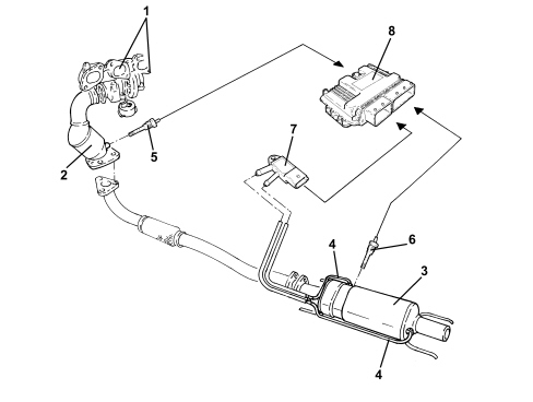
1. Turbocharger-exhaust manifold assembly
2. Catalytic converter
3. Filter
4. Exhaust gas pressure intake
5. Exhaust gas temperature sensor downstream of the catalyzer
6. Exhaust gas temperature sensor downstream of the filter
7. Differential pressure sensor
8. Injection control unit
Parts & tools for this job Staging For 2005 Alfa Romeo 159
- PARTExhaust gasketSearch: Alfa Romeo 159 2005 exhaust gasket
- TOOLPenetrating oilSearch: penetrating oil
- TOOLOBD2 scannerSearch: OBD2 scanner
Links open Amazon search results in a new tab. As an Amazon Associate I earn from qualifying purchases.