
E3580 Mobile telephone arrangement (Euro3)
- Make
- Alfa Romeo
- Model
- 156 Factory Service Manual
- Year
- 1997–2002
- Section
- Radio accessories › E3580 Mobile telephone arrangement (Euro3)
E3580 Mobile telephone arrangement (Euro3)
Description
The vehicle is also available, on request, prepared for the installation of a cellular telephone.
This preparation consists of:
- a special aerial, in the rear part of the roof;
- a hands-free speaker, located in the passenger door. It is the same speaker as for the radio with two connections: one specifically for the radio and another for the cellular phone hands-free function.
- Supply connection for recharging the mobile phone; located near the radio and also acts as a mount for the phone
- connecting cables for the aerial, radio, speaker and vehicle electrical supply.
Note
a microphone to complete the hands-free function does not come with this equipment because it is provided in the telephone connection kit and should be positioned at will.
The mobile phone connection has two power supplies; one direct and one ignition-operated; it also has a supply with the side lights on, to light up the telephone, if prepared.
The operation of the telephone, temporarily switches off the radio (MUTE function).
The above two lines are protected by two fuses in the junction unit.
Description of operation
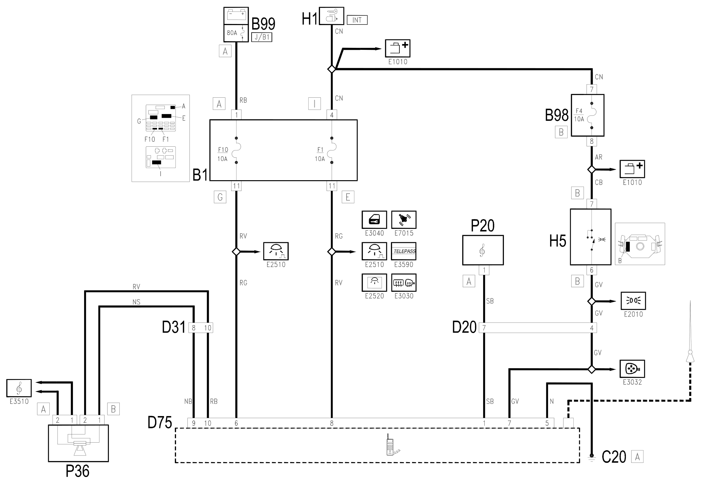
The connector D75 receives a supply directly (pin 6) from the battery via the line for fuse F10 of the junction unit B1 and the maxifuse J/B1 of B99.
It receives a supply controlled by the ignition (INT) (pin 8) via the line for fuse F1 of the junction unit B1.
With the side lights switched on, the supply reaches pin 7 by means of the line coming from the switch for the steering column switch unit H5, protected by fuse F4 of the additional fuse box B98 B.
Pin 5 of connection D75 is earthed, whilst pins 9 and 10 provide the signal for the speaker P36, connector B, whilst connector A is for the radio Wiring diagram E3510 CAR RADIO .
Lastly, pin 1 is connected to the radio P20 (MUTE function).
Wiring diagram
Components
| Code | Component | See |
|---|---|---|
| B01 | Junction unit | description 5505A |
| B05 | MAXI FUSE-1 box | |
| B11 | Controls lighting fuse | |
| B98 | Supplementary fuse box | description 5505A |
| B99 | Maxifuse box on battery | |
| C20 | Passenger side dashboard earth | description 5505A |
| D20 | Dashboard/rear connection | |
| D30 | Rear / front door connection left | |
| D31 | Right front door rear coupling/. | |
| D75 | Radio 'phone junction | |
| H01 | Ignition switch | description 5520A |
| H05 | Steering column switch unit | description 5550A |
| P20 | Car radio | description 5570T |
| P35 | Speaker on front door left | description 5570T |
| P36 | Speaker on front right door | description 5570T |
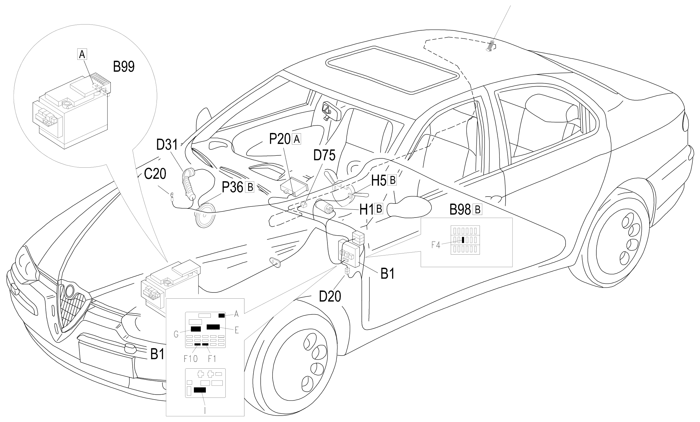
Component location
Parts & tools for this job Staging For 1997 Alfa Romeo 156
- TOOLDigital multimeterSearch: automotive digital multimeter
- PARTAssorted fuse kitSearch: car fuse assortment kit
- TOOLWire crimper and connector kitSearch: wire crimper connector kit
Links open Amazon search results in a new tab. As an Amazon Associate I earn from qualifying purchases.