
E1010 Power supply (from 2/99)
- Make
- Alfa Romeo
- Model
- 156 Factory Service Manual
- Year
- 1997–2002
- Section
- Power supply and ground › E1010 Power supply (from 2/99)
E1010 Power supply (from 2/99)
Description
The entire electrical system has been designed and constructed in accordance with the most up-to-date guidelines concerning safety and protection, especially against fire risks.
There are two main kinds of protection:
- active protection, aimed at reducing possible causes of faults 'at source';
- passive protection, aimed at minimizing the effects of a possible fault.
The first category involves careful design of wiring with thorough positioning and anchorage. Wiring is shielded and protected and the routes are carefully determined.
Modifications have therefore been made to the alternator and starter motor cables, with the adoption of protective caps, etc.
Passive protection instead includes all the interventions, which have always been adopted on vehicles, to reduce high fault currents (overload and short circuit).
All the fuses included in the system have been rated on the basis of the nominal absorption of the loads which cannot be served simultaneously, and so as to ensure intervention in the case of a definite short circuit.
All the electrical systems are supplied by the battery at a voltage of 12. V.
The battery is, in turn, recharged by the alternator Wiring diagram E5010 IGNITION AND RECHARGING during engine operation.
The main supply lines are protected by maxifuses, grouped together in a box directly on the positive battery terminal and connected directly to it.
The box contains up to eight maxifuses
The power supplies to all services and systems are protected by fuses grouped in the junction unit or in two special multiple connectors, one for the front wiring and other other for the facia wiring in accordance with a pre-established order.
All the power supplies are thus protected, except for the starter motor cable (battery-starter motor) and recharging cable (starter motor-alternator): these are protected by an additional shielded sheath.
Some circuits are supplied continuously, even if the vehicle is stopped and the ignition is off, as they are connected directly to the battery.
Other circuits are supplied by turning the ignition key to various different positions:
- when the key is inserted and turned to the first click, the ignition is turned on (ON position) and several circuits are supplied, which are thus called 'ignition-operated' (lines 'INT' and '15/54');
- the second click - AVV position - instead supplies the starter motor (line '50')., disconnecting some circuits (those which absorb most power), thus ensuring the maximum flow of current to the starter motor; ('INT/A' line).
- on the other hand, by extracting the key and turning it in the opposite direction (and pressing the special button) the PARK position is engaged which supplies the side lights even with the key switched off ('STAZ' and 'POS' lines); Wiring diagram E2010 SIDE LIGHTS / NUMBER PLATE
Note
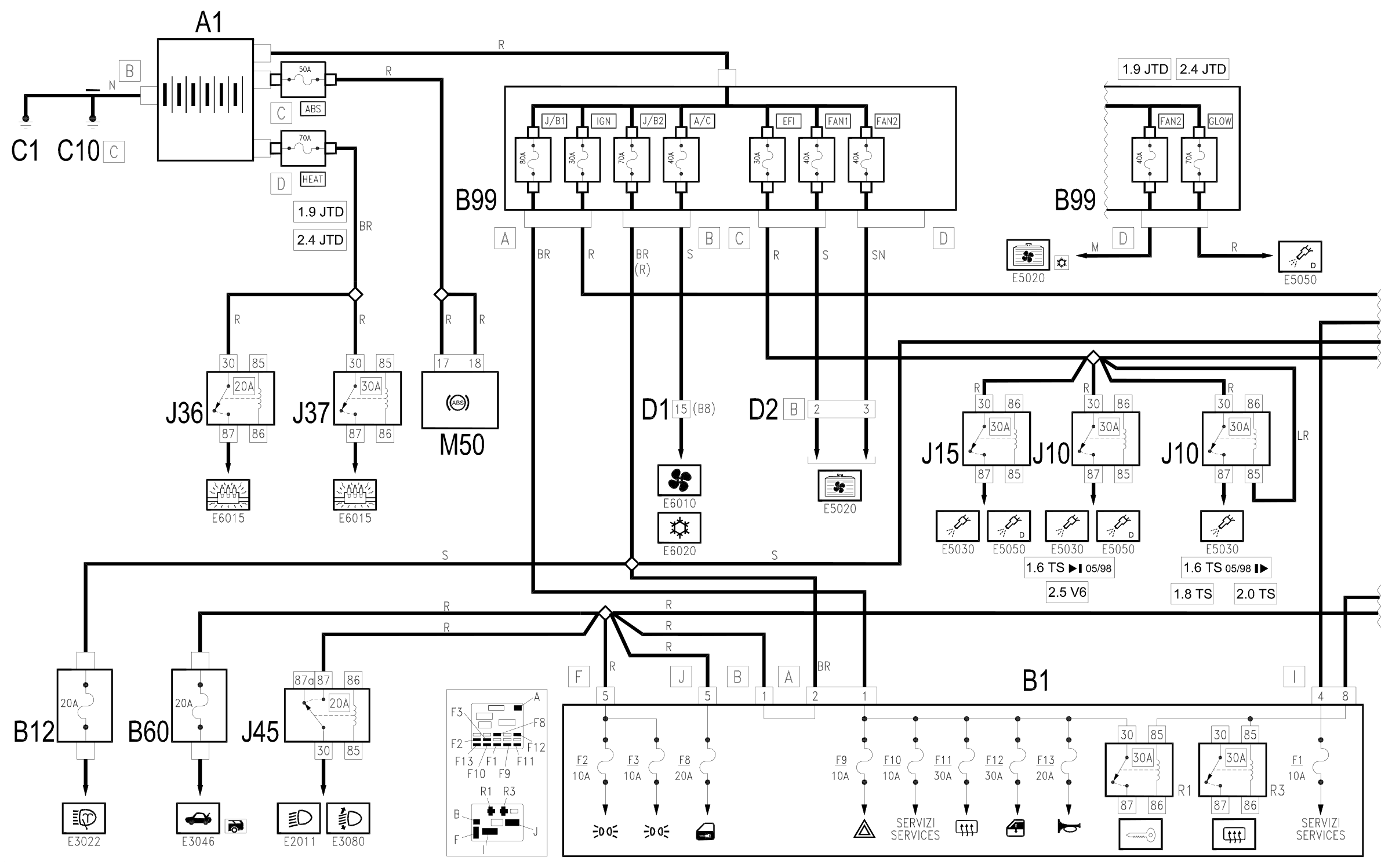
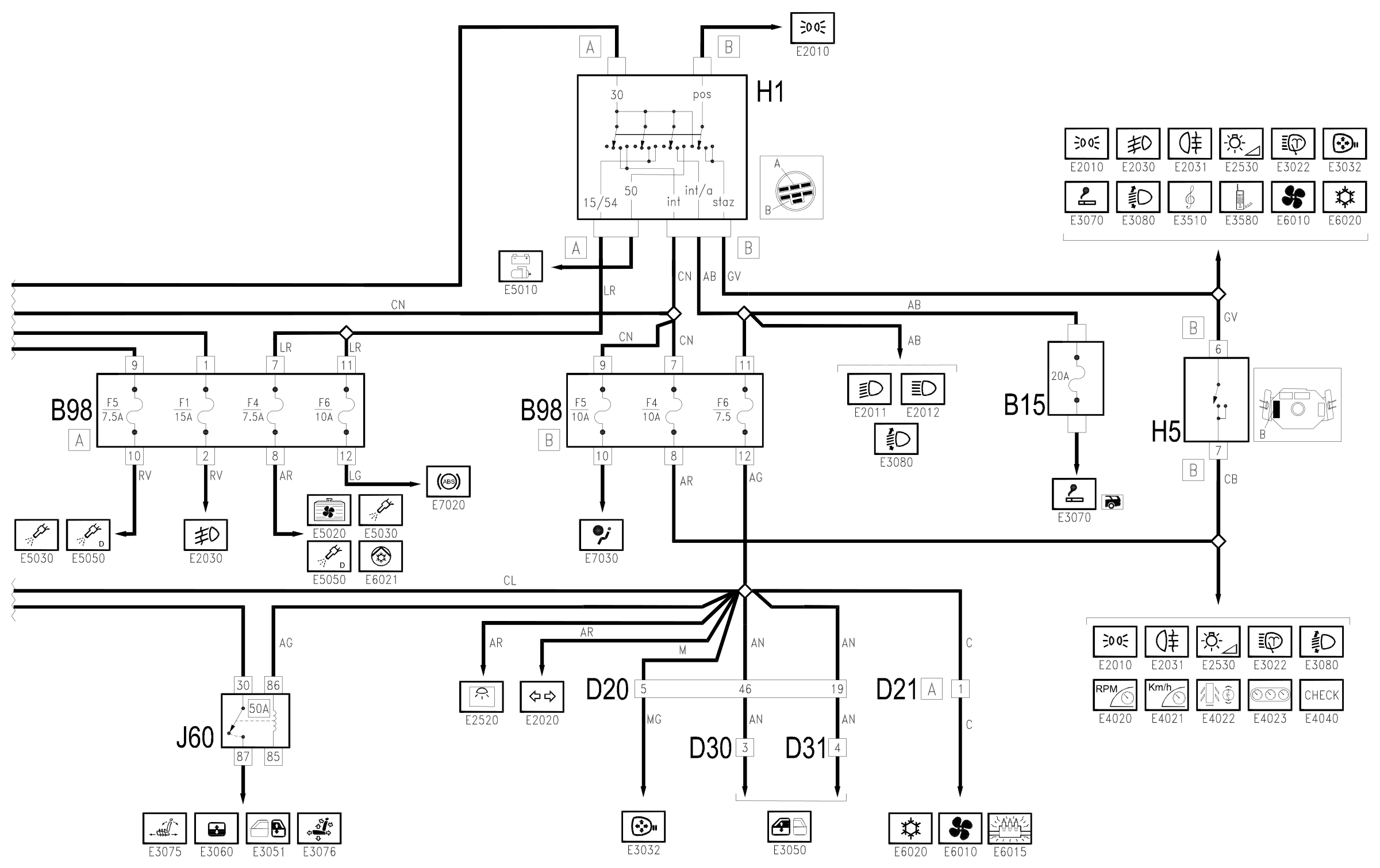
The lines through which the supply is distributed to the various electrical devices are shown on the wiring diagrams relating to the various functions and systems.
This general diagram shows all the lines which depart from the battery and the MAXIFUSE boxes; reference should be made to the specific diagrams for greater detail.
Description of operation
All the electrical equipment and systems are supplied by the battery A1.
The main supply lines are protected by the MAXIFUSE box B99 which contains the fuses named according to the circuits protected:
- J/B1: supply for services through the junction unit
- IGN: ignition switch supply;
- J/B2: supply for services through the junction unit
- A/C: air conditioning system supply
- EFI: supply for fuses and relays for engine management
- FAN1: engine cooling fan supply;
- FAN2: engine cooling fan supply
- GLOW: diesel glow plugs supply
The fuse box also contains two 'MIDI' fuses located directly on the battery and named according to the circuits protected.
- ABS: supply to ABS: A1, connector C.
- JTD versions
- HEAT: additional heater supply: A1, connector D
Other circuits are supplied by turning ignition key H1 to various different positions:
- in the ON position, numerous circuits and services controlled by the ignition (INT line) are supplied.
- in the AVV position - the starter motor is supplied; (line '50') ( Wiring diagram E5010 IGNITION AND RECHARGING ): In this position several circuits are disconnected (line 'INT/A'.
- in the PARK position the side lights are supplied ('STAZ' and 'POS' lines); Wiring diagram E2010 SIDE LIGHTS / NUMBER PLATE
Wiring diagram
Components
| Code | Component | See |
|---|---|---|
| A01 | Battery | description 5530B |
| B01 | Junction unit | description 5505A |
| B05 | MAXI FUSE-1 box | |
| B06 | MAXI FUSE box - 2 | |
| B10 | Key-dependent supply fuse (INT/A) | |
| B11 | Controls lighting fuse | |
| B12 | Headlamp washer fuse | |
| B13 | Fog lamp fuse | |
| B14 | Sun-roof fuse | |
| B17 | Rear electric windows fuse | |
| B20 | Seat heating fuse | |
| B25 | Ignition-dependent services supply fuse (15 / 54) | |
| B30 | ABS fuse and Air Bag | |
| B31 | ABS fuse | |
| B32 | Air Bag fuse | |
| B35 | Injection memory and CODE fuse | |
| B36 | Lambda sensor fuse | |
| B37 | Diesel plug and preheating fuse | |
| B38 | Additional heater fuse | |
| B39 | Diesel pre-heating fuse | |
| B40 | Fuel injection services supply fuse | |
| B41 | Fuel injection control unit supply relay | |
| B42 | Automatic transmission supply fuse | |
| B98 | Supplementary fuse box | description 5505A |
| B99 | Maxifuse box on battery | |
| C01 | Battery earth | description 5530B |
| C10 | Front left earth | description 5505A |
| D05 | Front / ABS couping | |
| H01 | Ignition switch | description 5520A |
| H05 | Steering column switch unit | description 5550A |
| J10 | Fuel injection main relay | |
| J15 | Fuel pump relay | |
| J36 | Additional heater relay - 1 | |
| J37 | Additional heater relay - 2 | |
| J40 | Foglamp relay | |
| J45 | Dipped beam maintenance relay | |
| J50 | Headlamp washer relay | |
| J60 | Optional services relay | |
| M50 | ABS control unit | description 3340A |
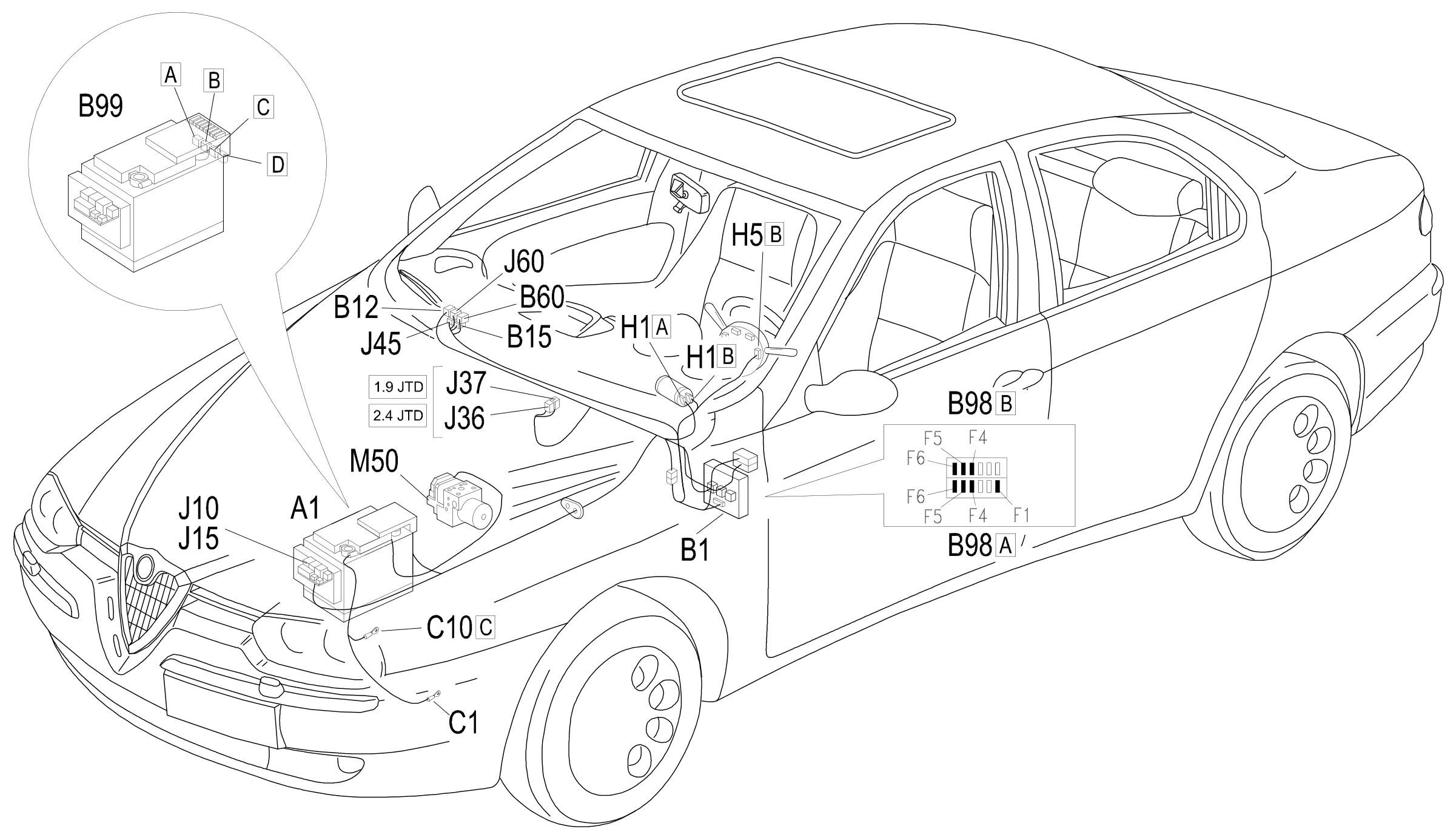
Component location
Parts & tools for this job Staging For 1997 Alfa Romeo 156
- TOOLDigital multimeterSearch: automotive digital multimeter
- PARTAssorted fuse kitSearch: car fuse assortment kit
- TOOLWire crimper and connector kitSearch: wire crimper connector kit
Links open Amazon search results in a new tab. As an Amazon Associate I earn from qualifying purchases.