
E2021 Stop light (Euro3)
- Make
- Alfa Romeo
- Model
- 156 Factory Service Manual
- Year
- 1997–2002
- Section
- Exterior lighting › E2021 Stop light (Euro3)
E2021 Stop light (Euro3)
Description
The brake lights are located at the rear in the side lights and in the central third brake light and consist of 10 separate bulbs.
These are operated whenever the brake pedal is pressed, by means of a switch on the pedal itself.
The correct operation of the side brake lights is controlled by the check device for the exterior lights, located inside the rev counter module.
The following faults may occur:
- blown bulb
- bulb s.c. to earth or positive
- incorrect bulb (5W bulb instead of 21W)
A special failure warning light, also in the rev counter module, comes on for all other faults in the various circuits. This warning light comes on for about 4 seconds when the ignition key is turned to MAR, to indicate it is working properly, then it goes off.
The third centre brake light is not controlled by the check panel.
The circuit is protected by the two fuses for the lights controlled by the check panel, one for the lights on the right hand side, the other for those on the left hand side and by a fuse on the supply line for all three brake lights.
A braking signal is also sent from the switch to the ABS, which detects braking status and therefore introduces braking control. The same signal is also sent to some engine management systems, which take the braking condition into account when determining the engine control mode.
Description of operation
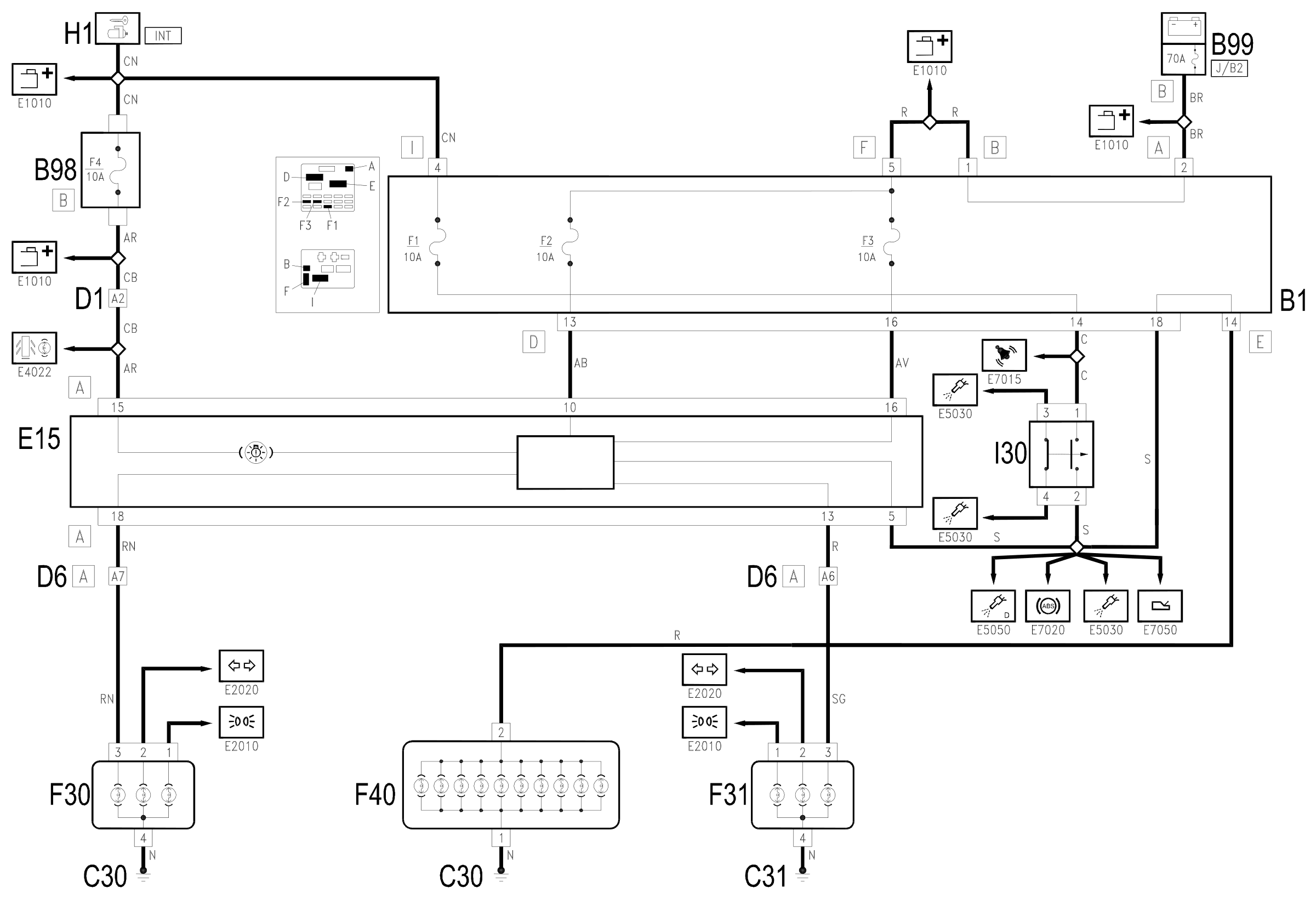
The switch I30 is controlled by the ignition (INT)from the line for fuse F1 for the control unit B1: when the brake pedal is pressed, the switch closes and sends the operating signal to the check device inside the rev counter E15 (pin 5 of connector A).
The supply for the check device inside E15 arrives directly from the battery (maxifuse B99) at pins 10 and 16 of connector A, through fuses F2 and F3 of the junction unit B1; The former protects the left hand lighting circuits, the latter protects the right hand circuits.
The check device thereby controls the supply (pin 18 and pin 13 of connector A) for the side brake lights in the rear light clusters F30 and F31.
In the case of failures in the circuit, the 'lights failure' warning light - inside E15 - comes on, with the supply controlled by the ignition (IINT), pin 15 of connector A, of the line protected by fuse F4 of the additional fuse box B98B.
The switch I30 sends the signal for operating the centre rear light cluster F40 via the junction unit B1 (pin 18, connector D and pin 14 of connector E).
The braking signal for the switch I30 is sent from the switch to the ABS Wiring diagram E7020 ABS and - on some versions - to the engine management control unit as well.
Wiring diagram
Components
| Code | Component | See |
|---|---|---|
| B01 | Junction unit | description 5505A |
| B05 | MAXI FUSE-1 box | |
| B11 | Controls lighting fuse | |
| B98 | Supplementary fuse box | description 5505A |
| B99 | Maxifuse box on battery | |
| C30 | Left rear earth | description 5505A |
| C31 | Rear right earth | description 5505A |
| D01 | Front / dashboard connection | |
| D06 | Front / rear connection | |
| D87 | Left tailgate rear coupling/ | |
| E15 | Rev counter | description 5560B |
| F30 | Rear lights cluster left (fixed part) | description 5540A |
| F31 | Rear right lights cluster (fixed part) | description 5540A |
| F40 | Additional tail-light ('third brake light') | description 5550D |
| H01 | Ignition switch | description 5520A |
| I30 | Brake pedal switch | description 5550D |
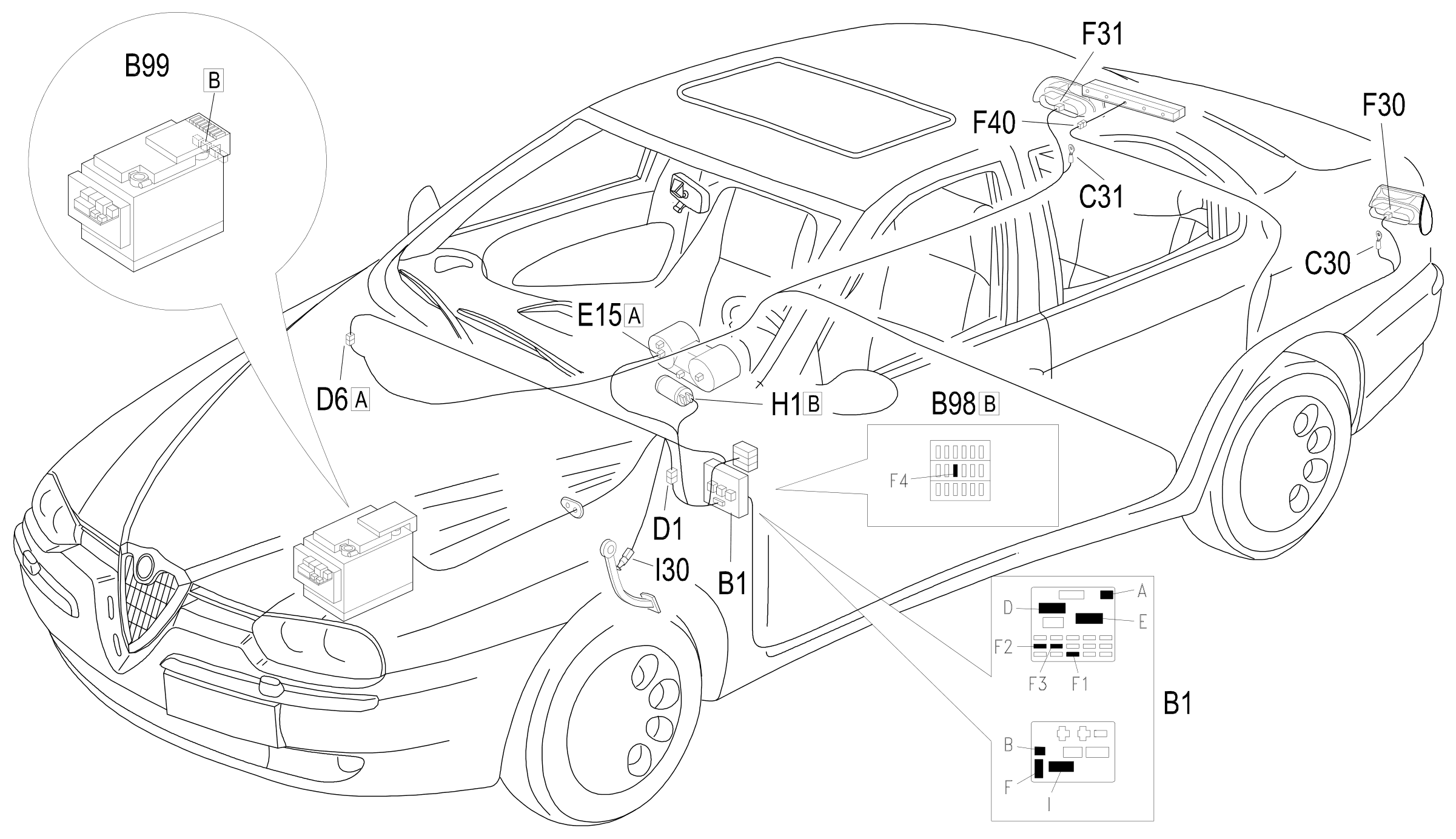
Component location
Parts & tools for this job Staging For 1997 Alfa Romeo 156
- PARTReplacement bulbsSearch: Alfa Romeo 156 1997 bulbs
- TOOLDigital multimeterSearch: automotive digital multimeter
Links open Amazon search results in a new tab. As an Amazon Associate I earn from qualifying purchases.